Tutorials
Learn the simulator, part by part
Written guides with real screenshots of the lab. Start with the first circuit, then pick any component: each guide shows the block, its pins, how to wire it, what its settings do, the code that drives it and what to expect when it runs.
Getting started
The lab itself: how to place parts, wire them, write code, run it and keep your work.
-
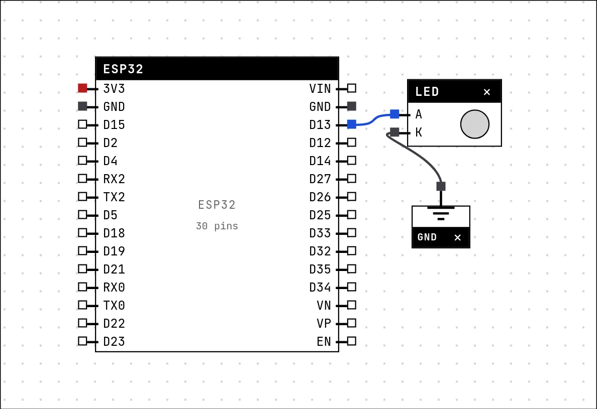 Your first circuit: blink an LEDFrom an empty canvas to a blinking LED — placing a part, drawing wires, writing the code, saving and running. Ten minutes, and you will have used every part of the lab once.
-
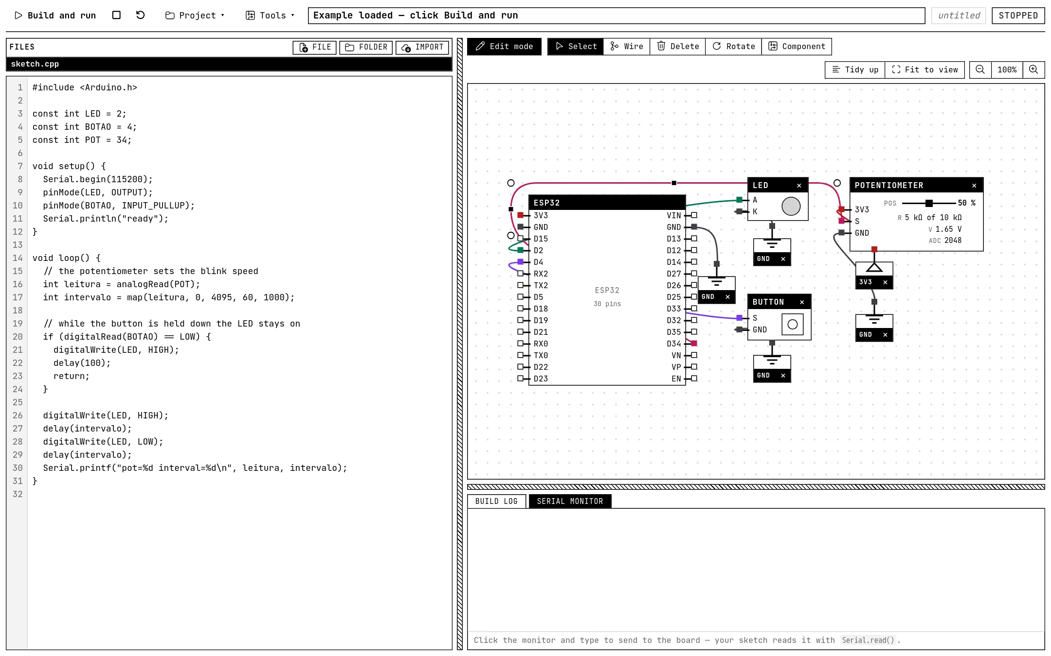 A tour of the labEvery area of the screen and what it is for: the top bar, the files and the editor, the canvas and its toolbar, the output panel, and the datasheet card.
-
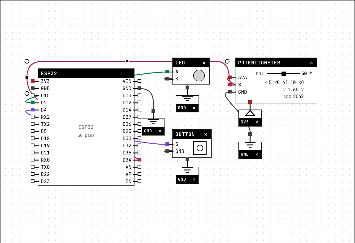 Placing parts and wiringThe catalog, the Wire tool, junctions and free tracks, nets and their colors, the ground and power symbols, and the tools that move, rotate and delete.
-
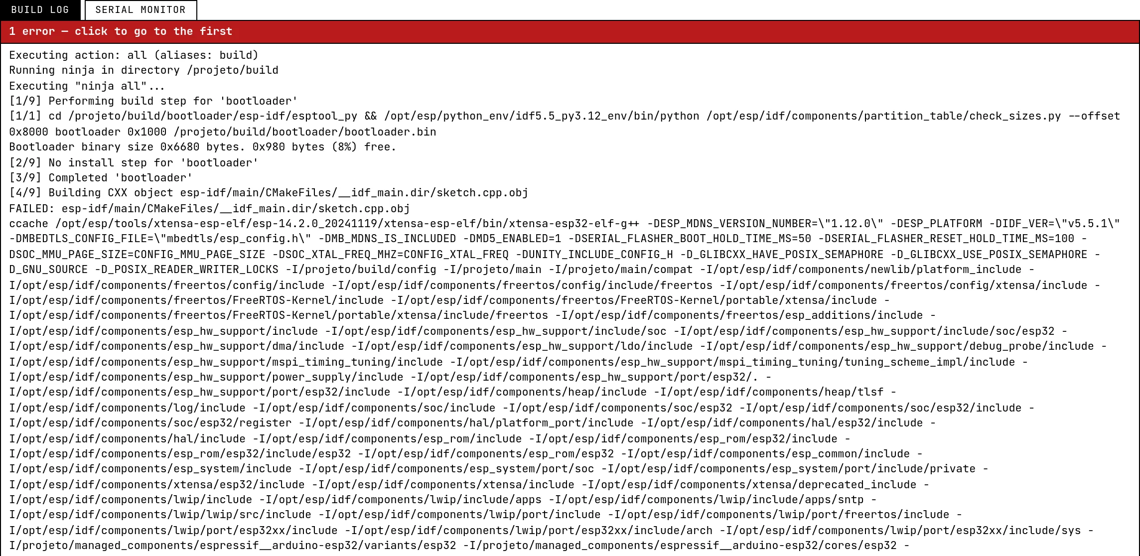 Build, run and read the logWhat happens when you press Build and run, the states of the simulation, the build log and its clickable errors, stop and restart, and why a build can wait in a queue.
-
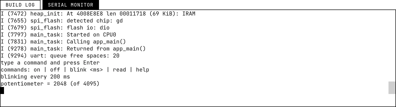 The serial monitorReading what the firmware prints, typing to the board, and an example that takes commands from the monitor.
-
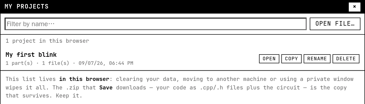 Projects, files and examplesWhere your work lives, how Save and Open work, files and folders in a project, the examples gallery and the keyboard shortcuts.
-
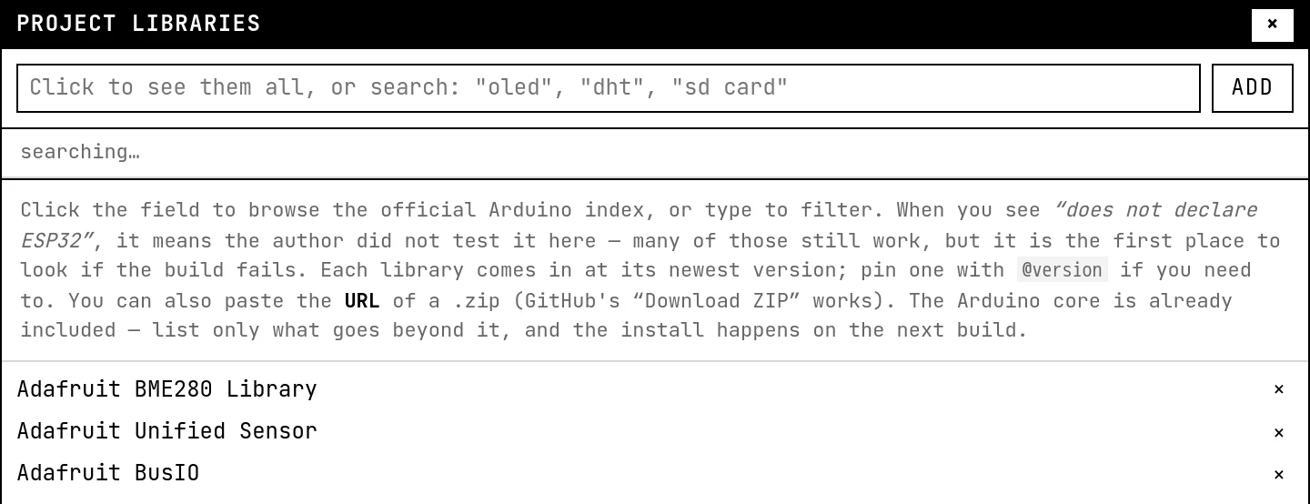 Project librariesAdding an Arduino library to a project: searching the official index, pinning a version, using a .zip from a URL, and what happens on the next build.
Boards
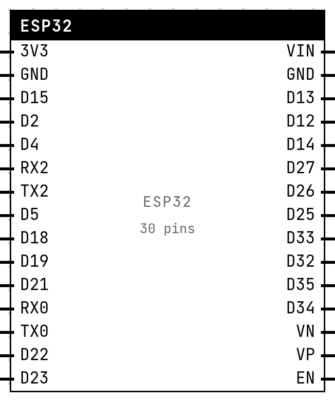
Which board to pick, and what every pin on its header does.
Power & measuring
GND and 3V3, the adjustable supply, the voltmeter and the voltage divider — and the warnings that keep a real board alive.
-
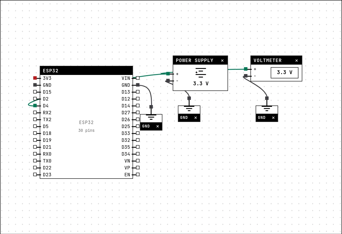 Power, ground and the voltmeterThe GND and 3V3 symbols, the adjustable power supply, the voltmeter, and the electrical warnings the lab raises when a wire would damage the board.
-
 Voltage divider and the voltmeterA potentiometer as a divider on an ADC pin, with a voltmeter on the wiper: what the code reads, what the block shows, and what the meter can and cannot see.
Output
Things the code drives: lights, sound, motion, displays.
-
 LEDThe first output of every project: a GPIO set HIGH lights it, LOW turns it off.
-
 RGB LEDThree LEDs in one package, one GPIO each — red, green and blue mix into eight colors.
-
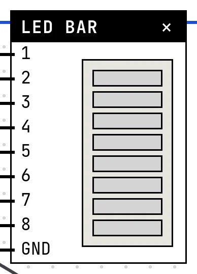 LED barA row of 2 to 16 LEDs, one GPIO each — the level meter of every stereo.
-
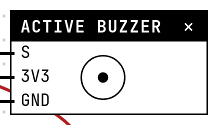 Active buzzerA beeper with its own fixed tone: HIGH sounds it, LOW silences it — and it really sounds in your browser.
-
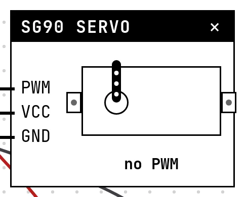 SG90 servoA 9 g micro servo whose arm follows the width of the pulse it receives — the block shows the pulse it measures.
-
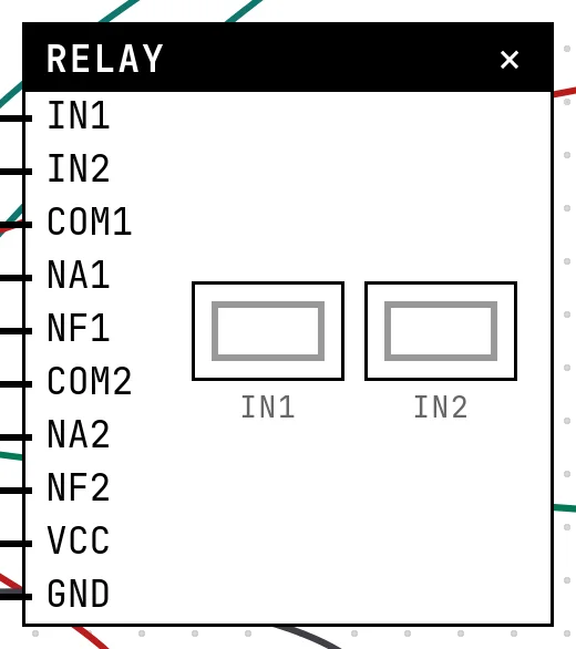 Relay, lamp and the mainsThe electromechanical switch that lets a 3.3 V pin drive a lamp on the mains — with the AC side kept away from the board.
-
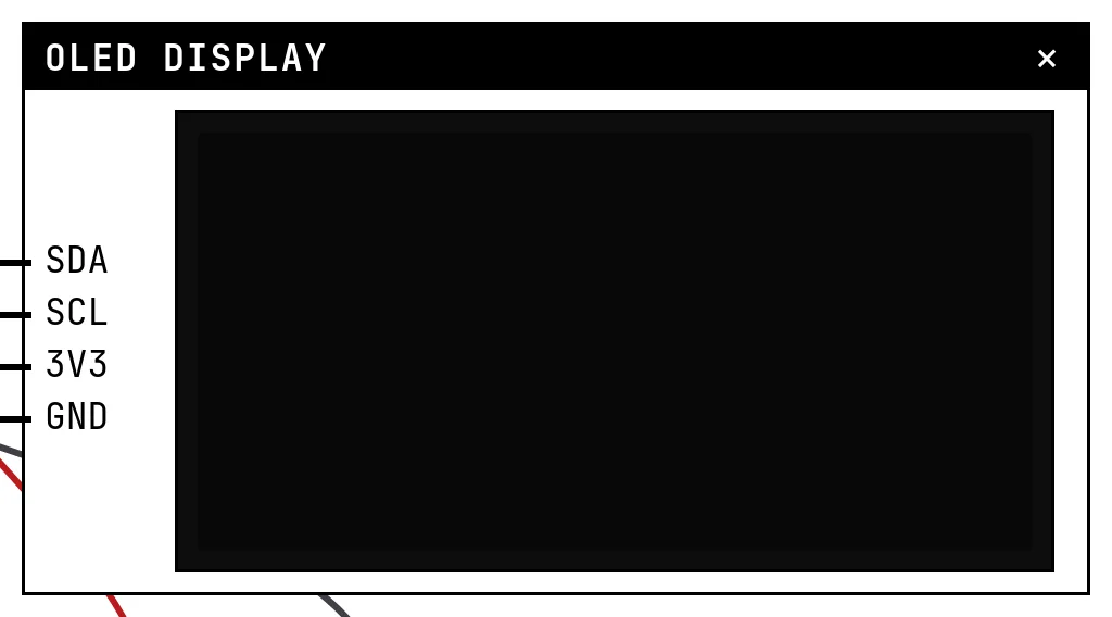 OLED display (SSD1306)The 0.96″ 128×64 screen on I²C: two wires, an address, and a library that draws text and shapes.
-
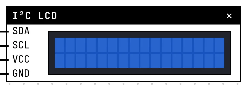 Character LCD with I²C backpackThe classic 16×2 text display cut down to two wires by a small I²C board — text, custom characters and a backlight.
-
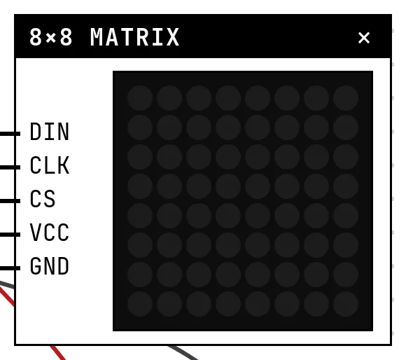 8×8 LED matrix (MAX7219)Sixty-four LEDs driven through three wires by a MAX7219 — pixel art in eight bytes.
-
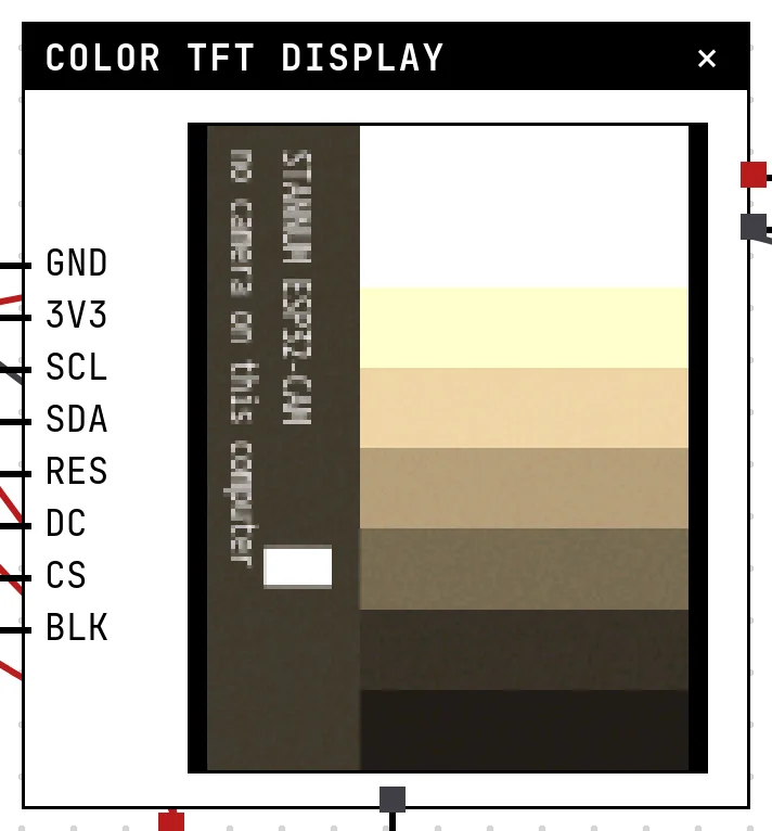
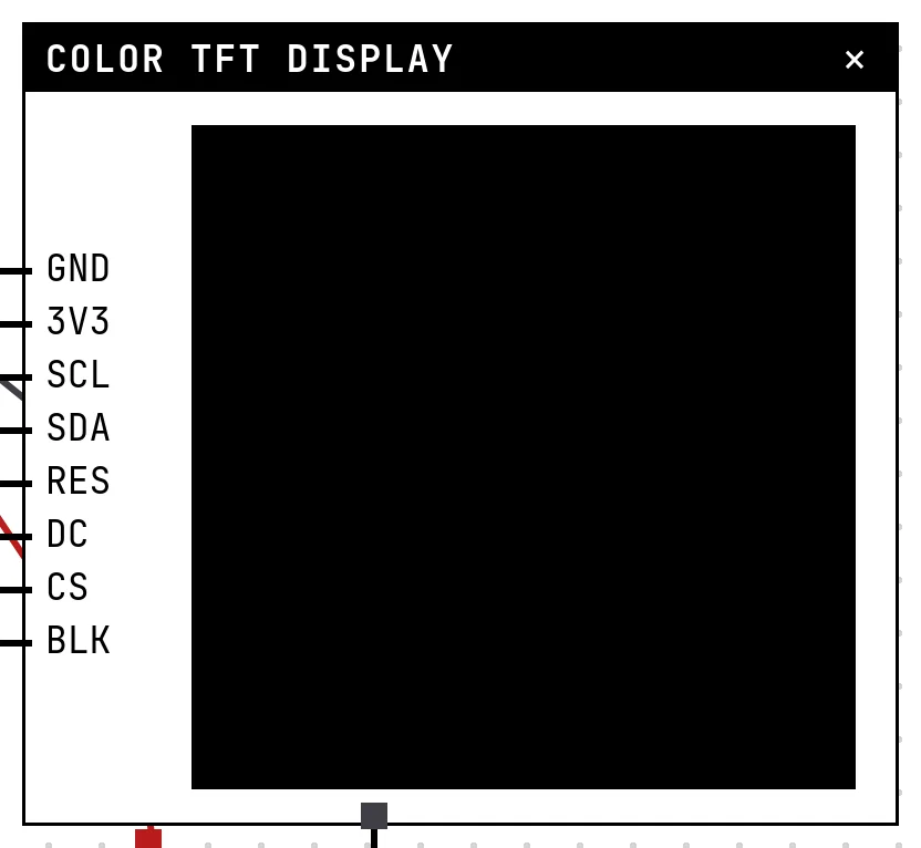 Color TFT display (ST7735 / ST7789)The 7-pin SPI color screen in five sizes, from 80×160 to 240×320, with the quirks of the real controller — including the white screen of a wrong init.
Input
Things you operate on the canvas and the code reads.
-
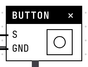 Push buttonA momentary contact: HIGH while released, LOW while pressed — the first digital input.
-
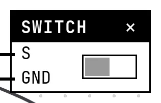 Slide switchA contact that stays where you leave it — on/off state, read like a button.
-
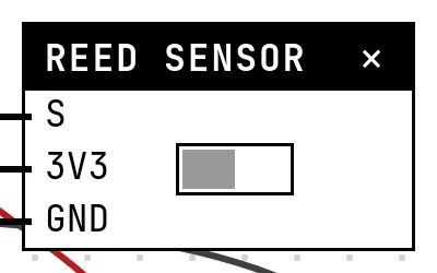 Reed switchA contact that closes near a magnet — the sensor on every door and window alarm.
-
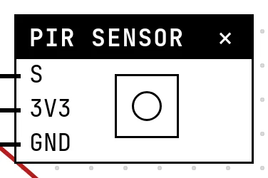 PIR motion sensorThe HC-SR501: it raises its output for a few seconds when something warm moves in front of it.
-
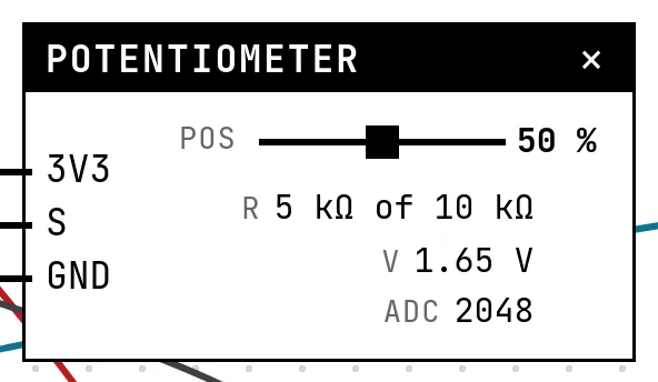 PotentiometerA variable resistor whose wiper divides 3.3 V — the first analog input, read with analogRead().
-
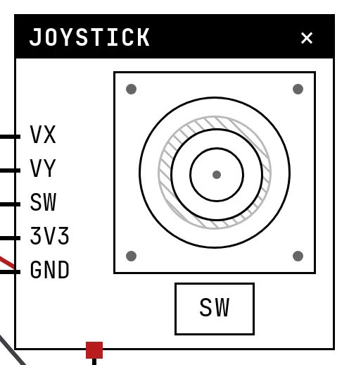 Analog joystickTwo potentiometers and a button in one stick: two ADC channels and one digital input.
-
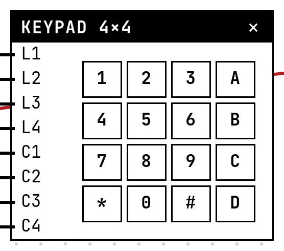 4×4 matrix keypadSixteen keys on eight wires: the code scans rows and columns, and the simulation closes the right crossing.
-
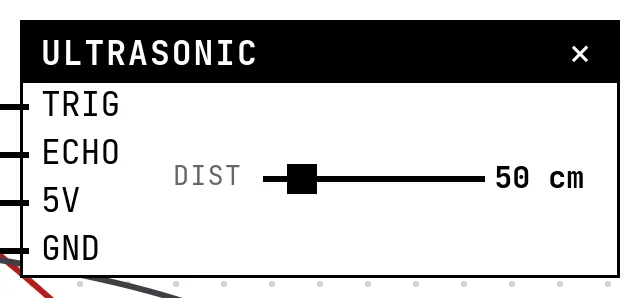 Ultrasonic distance sensor (HC-SR04)Trigger a ping, time the echo: 58 microseconds per centimeter, measured by the firmware itself.
Sensors
Physical quantities you set on the block, read by the code the way a real sensor would report them.
-
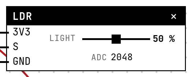 LDR (photoresistor)A resistor that drops with light — read through the ADC as a number that grows with brightness.
-
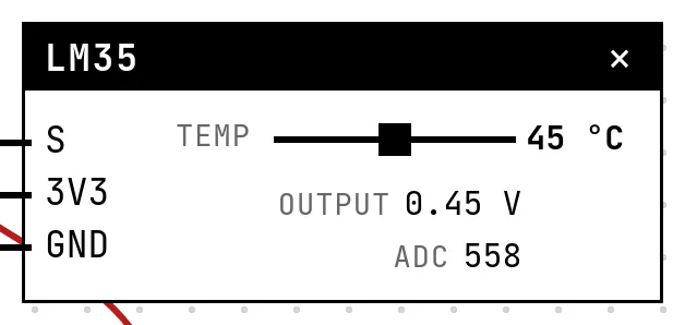 LM35 temperature sensorTen millivolts per degree, straight from the sensor: read the voltage, multiply by 100.
-
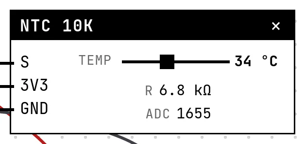 NTC thermistorA resistor that shrinks as it heats — cheaper than the LM35, but the code has to undo a curve.
-
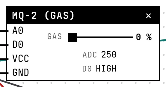 MQ-2 gas and smoke sensorAn analog reading that rises with gas, plus a digital alarm output with a threshold you set on the module.
-
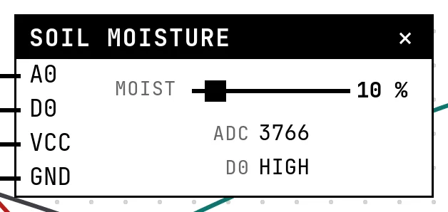 Soil moisture and rain sensorsTwo resistive boards with the same electronics: a dry board reads HIGH, and a comparator gives a digital alarm.
-
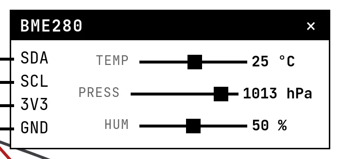 BME280 environmental sensorTemperature, pressure and humidity from one I²C chip, read by the real Adafruit library — calibration and all.
-
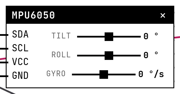 MPU6050 accelerometer and gyroscopeSix axes on I²C: at rest the accelerometer measures gravity, and tilting redistributes it — that is how a phone knows it was turned.
-
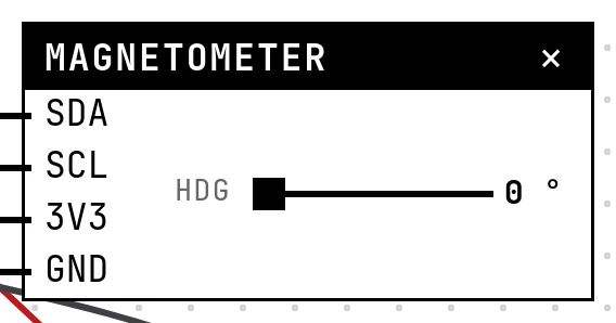 Magnetometer (HMC5883L compass)Three magnetic axes on I²C; atan2 of X and Y is the heading — the electronic compass, without a library.
-
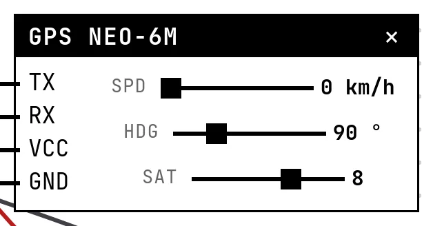 GPS receiver (NEO-6M)A module that talks on its own: NMEA sentences on a serial port, once a second, decoded with TinyGPS++.
Camera
The ESP32-CAM, with its frames coming from your computer's camera.
Storage
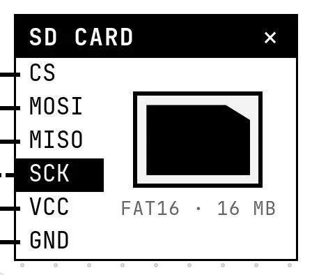
Files that survive a restart, on a card you can eject.
Connectivity
Wi-Fi to the real internet, messages through a broker, and radio with no network at all.
-
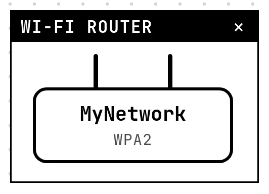 Wi-Fi and the routerThe ESP32 only connects if there is a router block with the right name and password — and then it reaches the real internet.
-
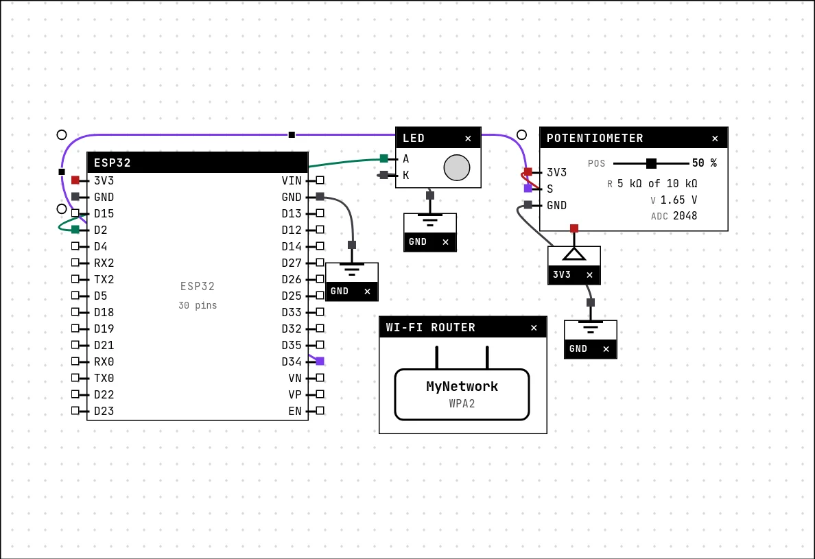 MQTT: readings to the cloud and backPublish a potentiometer reading to a public broker on the internet every three seconds, subscribe to the same topic, and blink an LED when the message comes back.
-
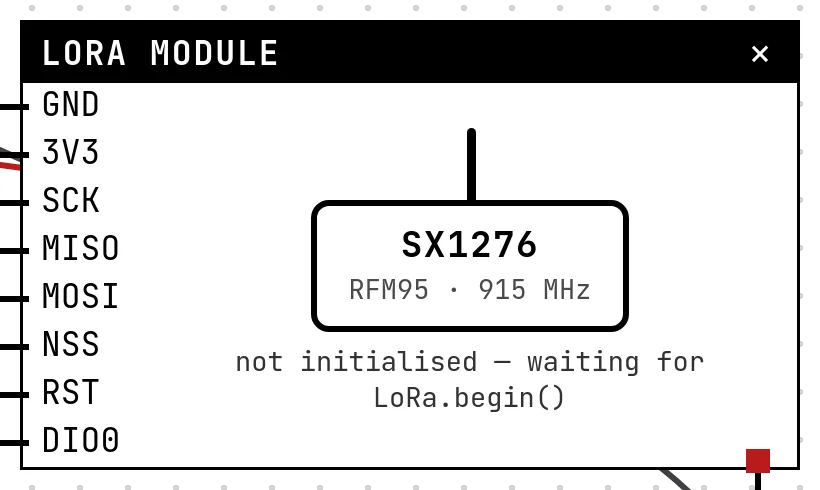 LoRa radioAn SX1276/SX1278 module talking to a second radio kilometres away — no network in between, and every packet accounted for.