Tutorials / Connectivity
LoRa radio
An SX1276/SX1278 module talking to a second radio kilometres away — no network in between, and every packet accounted for.
- LoRa module
- LoRa node
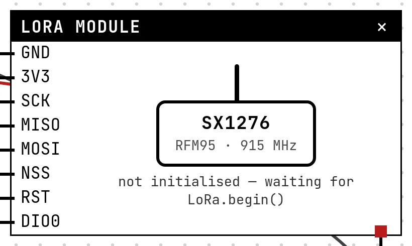
What it is
LoRa is long-range, low-rate radio: a few bytes at a time, kilometres apart, with no router or network. Two radios hear each other only if four parameters match — frequency, spreading factor, bandwidth and sync word — and if the distance leaves enough signal. The Ra-02 (433 MHz) and the RFM95 (915 MHz) are the same chip family in different bands; the LoRa library by Sandeep Mistry drives both.
In the simulator
Two blocks. The LoRa module is the radio wired to the ESP32; its Settings pick the band (RFM95 at 915 MHz or Ra-02 at 433 MHz), and its face shows what the code configured — frequency, SF, bandwidth, sync word and the current mode. The LoRa node is the other radio, somewhere on the air: its Settings are its own four parameters, a slider sets the distance (0.1 to 30 km), a field lets you send a packet to the ESP32, and its diary lists every packet on the air with its fate — heard, with RSSI and time on air, or lost, with the reason.
Pins
| Pin | What it is |
|---|---|
| GND | ground — to a GND symbol |
| 3V3 | power — to a 3V3 symbol |
| SCK | SPI clock — to GPIO 18 (VSPI) or 14 (HSPI) |
| MISO | SPI data from the radio — to GPIO 19 (VSPI) or 12 (HSPI) |
| MOSI | SPI data to the radio — to GPIO 23 (VSPI) or 13 (HSPI) |
| NSS | chip select — to a GPIO (5 in the example) |
| RST | reset — to a GPIO |
| DIO0 | interrupt: packet sent / packet received — to a GPIO |
Wiring
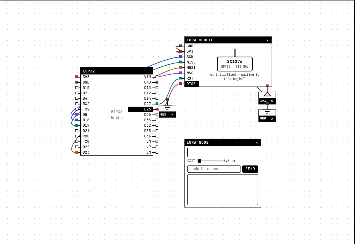
The circuit below is the example LoRa: talk to another radio from the lab — open it with Project → Open example… and it comes ready to run.
| LoRa module pin | Goes to |
|---|---|
| GND | a GND symbol |
| 3V3 | a 3V3 symbol |
| SCK | D18 on the board (GPIO 18) |
| MISO | D19 on the board (GPIO 19) |
| MOSI | D23 on the board (GPIO 23) |
| NSS | D5 on the board (GPIO 5) |
| RST | D27 on the board (GPIO 27) |
| DIO0 | D26 on the board (GPIO 26) |
The radio sits on VSPI (18, 19, 23) with NSS on 5, plus RST and DIO0 on two more GPIOs. The node has no wires: place it anywhere.
Settings
Double-click the block's title bar to open its card, then the Settings tab. Changes apply to the running simulation right away.
| Setting | Accepts | Default | Notes |
|---|---|---|---|
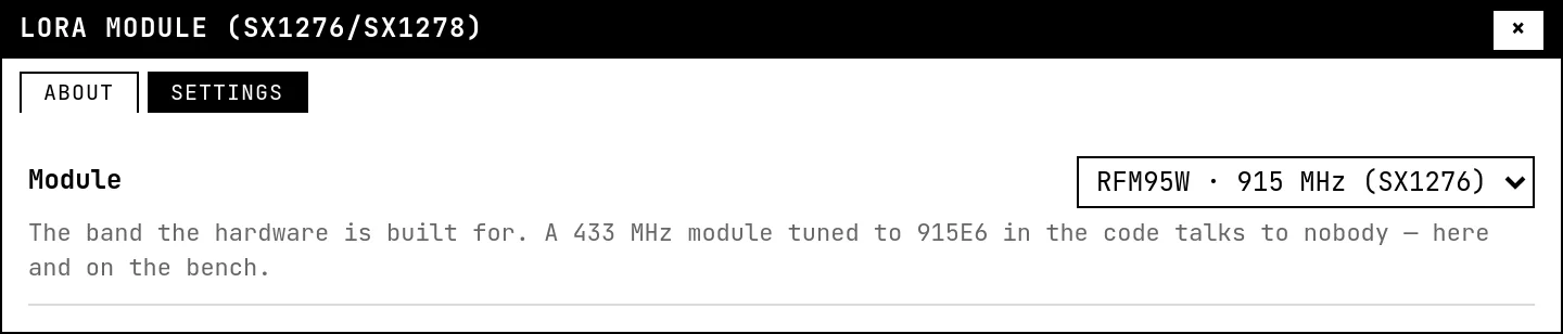
| Module | RFM95W · 915 MHz (SX1276) · Ra-02 · 433 MHz (SX1278) | RFM95W · 915 MHz (SX1276) | The band the hardware is built for. A 433 MHz module tuned to 915E6 in the code talks to nobody — here and on the bench. |
Code
// LoRa: talk to another radio
//
// Sends a numbered "ping" every 3 s and prints anything it receives, with the
// signal strength. The other radio is the "LoRa node" block in the circuit:
// it only hears this board if frequency, spreading factor, bandwidth and sync
// word match — set them on the node's card to the values below, and try
// changing one to see the packets get lost.
//
// Wiring (VSPI): SCK→18, MISO→19, MOSI→23, NSS→5, RST→27, DIO0→26.
#include <Arduino.h>
#include <SPI.h>
#include <LoRa.h>

const int PIN_NSS = 5, PIN_RST = 27, PIN_DIO0 = 26;

// Must be inside the band of the module you picked on its card: 915E6 for the
// RFM95, 433E6 for the Ra-02. A wrong band compiles fine and talks to nobody.
const long FREQUENCY = 915E6;

void setup() {
  Serial.begin(115200);
  LoRa.setPins(PIN_NSS, PIN_RST, PIN_DIO0);
  if (!LoRa.begin(FREQUENCY)) {
    Serial.println("LoRa module not found — check NSS, RST and the SPI wiring");
    while (true) delay(1000);
  }
  // These four have to match the other radio. SF7 is fast and short-range;
  // SF12 takes 24x longer per packet and reaches much farther.
  LoRa.setSpreadingFactor(7);
  LoRa.setSignalBandwidth(125E3);
  LoRa.setSyncWord(0x12);
  LoRa.enableCrc();
  Serial.println("LoRa ready: 915 MHz, SF7, 125 kHz");
}

unsigned long lastSend = 0;
int counter = 0;

void loop() {
  // Receive: parsePacket() arms the radio and returns the size of a packet
  // that arrived. Keep the loop fast — the chip drops back to standby a few
  // hundred milliseconds after each parsePacket(), and a long delay() here
  // makes it deaf most of the time (on the bench too).
  int size = LoRa.parsePacket();
  if (size) {
    String text;
    while (LoRa.available()) text += (char)LoRa.read();
    Serial.printf("RX \"%s\"  RSSI %d dBm  SNR %.1f dB\n",
                  text.c_str(), LoRa.packetRssi(), LoRa.packetSnr());
  }

  // Transmit: endPacket() only returns after the packet really left — the
  // time on air (~30 ms at SF7 for this size, over a second at SF12).
  if (millis() - lastSend > 3000) {
    lastSend = millis();
    counter++;
    LoRa.beginPacket();
    LoRa.print("ping ");
    LoRa.print(counter);
    LoRa.endPacket();
    Serial.printf("TX ping %d\n", counter);
  }
}LoRa.setPins(NSS, RST, DIO0) and LoRa.begin(915E6); then beginPacket/print/endPacket to send and parsePacket to receive. The example pings the node, prints what comes back with packetRssi(), and its comments explain the trap of a receiver that spends its time in delay(): a radio only hears while it is listening.
Run it
Press Build and run. The first build of a project takes a while; after that, only what changed is rebuilt.
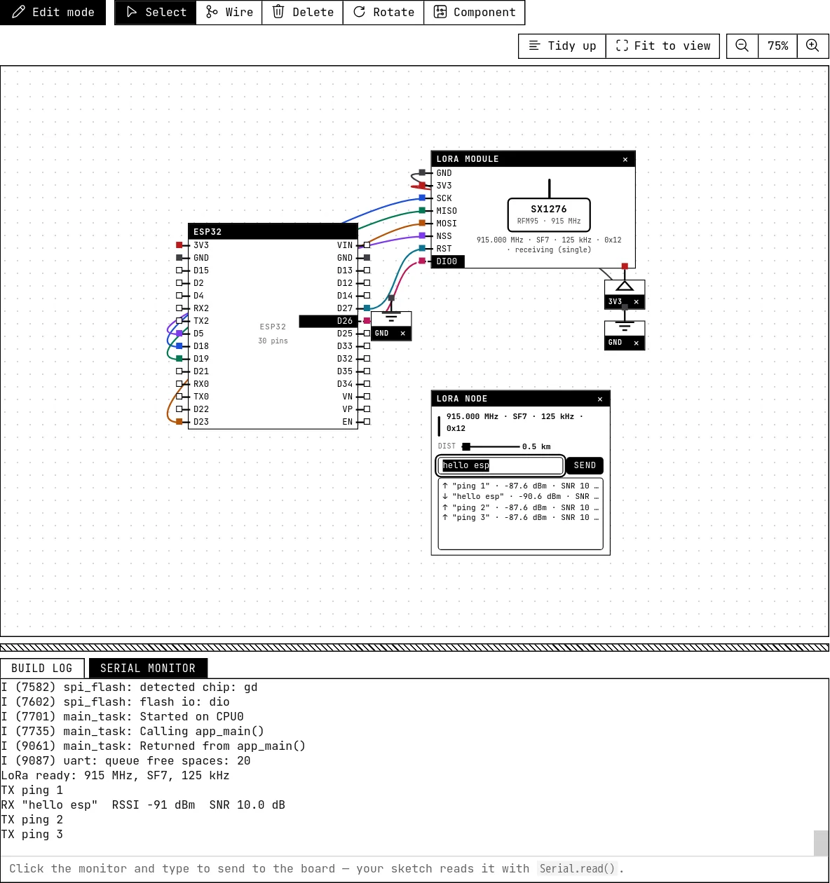
The node's diary shows each ping from the ESP32 with the signal strength at 500 m. Type “hello esp” in the node's field and press Send: the ESP32 prints it with the RSSI. Now drag the distance to 12 km, or change the node's spreading factor: the diary starts saying “lost”, and why.
How the simulation models it
- The chip is emulated at the register level (FIFO, modes, IRQ flags, DIO0 mapping, RSSI and SNR of the last packet), so the library works as on the bench, including
setSpreadingFactor,setSignalBandwidthandsetSyncWord. - Time on air follows the datasheet formula: 10 bytes at SF7/125 kHz take about 41 ms, at SF12 almost a second. Sending is not instantaneous, and the chip only hears the node if it is in receive mode when the packet starts.
- Range: the signal falls with a log-distance model (exponent 2.7, a suburban setting); a packet below the sensitivity of the configured SF is lost. SF7 dies around 8 km, SF12 reaches past 20 — the curve seen in practice. A module tuned outside its band talks to nobody.
- Mismatched frequency (beyond a quarter of the bandwidth), SF, bandwidth or sync word: silence on both sides, with the reason in the diary. Frame check, coding rate and preamble follow the library's defaults.
Try this
- Set the node to SF12 and the code to SF12 too, and watch the time on air in the diary jump.
- Send a temperature reading from the BME280 every 10 seconds instead of a ping.
- Leave the receiver in a 3-second
delay()and send from the node during it: the packet is lost — the diary says the radio was not listening.
See also
- Wi-Fi and the router — The ESP32 only connects if there is a router block with the right name and password — and then it reaches the real internet.
- BME280 environmental sensor — Temperature, pressure and humidity from one I²C chip, read by the real Adafruit library — calibration and all.