Tutorials / Camera
ESP32-CAM camera
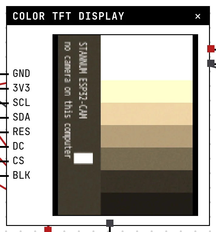
The camera board with the real esp_camera API, and a color display on its free pins showing every frame: the frames come from your computer's camera, reduced to exactly what the OV2640 sensor would deliver.
The AI-Thinker ESP32-CAM is an ESP32 with an OV2640 camera module on top. The firmware talks to it through the esp_camera library: configure the pins and the format, call esp_camera_fb_get(), and you get a frame buffer. In the lab the same code runs unchanged; what changes is where the picture comes from.
The board has no screen, and the block in the lab does not invent one. A frame lives in RAM until the code takes it somewhere — a display, an SD card, the network. The example wires a 1.8″ TFT to the board's free pins and draws every frame on it, which is how you see what the camera sees, here and on the bench.
How the simulation works
- Pick the ESP32-CAM as the board (its card → Settings → Board model). The block shows the board's pins, nothing else — as the board.
- When the firmware calls
esp_camera_init(), the lab asks the browser for this computer's camera. The browser asks you for permission; the image never leaves your simulation session, and the camera is released when the simulation stops. - No camera, or permission denied? The sensor sees a test pattern — color bars with a moving marker — so the code still gets frames.
- Every
esp_camera_fb_get()asks the browser for one frame. The browser crops the image to the sensor's aspect ratio, scales it down to the configured frame size (160×120 for QQVGA, 320×240 for QVGA…), applies the sensor settings the code chose — mirror, flip, brightness, contrast, saturation, the special effects — adds the softness and the grain of a small sensor, and delivers it in the configured format: RGB565 or grayscale pixels as the OV2640 lays them out, or a JPEG at the configured quality (the esp32-camera scale, 0 to 63, lower is better). That is the buffer the firmware receives, byte for byte. - What happens to the frame next is the code's business. The example sends it to the TFT over SPI, the same way the display guide shows.
What the library does here
| Call | In the simulator |
|---|---|
esp_camera_init(&config) | Accepts PIXFORMAT_JPEG, PIXFORMAT_GRAYSCALE and PIXFORMAT_RGB565. A raw format that would not fit the RAM (there is no PSRAM here, as on a bare board) fails with ESP_ERR_NO_MEM and a line explaining why. The pins are accepted and ignored: there is no bus to drive. |
esp_camera_fb_get() | Returns a camera_fb_t with buf, len, width, height and format — a real JPEG (starts with FF D8), or raw pixels for the raw formats, high byte first as the sensor sends them. NULL if the lab tab is closed or the frame does not fit the RAM. |
esp_camera_fb_return(fb) | Frees the buffer. Forgetting it leaks memory here as on the board. |
esp_camera_deinit() | Stops the camera. The driver cannot change the pixel format on the fly, here or on the board: to switch, deinit and init again — the example does exactly that for its jpeg command. |
esp_camera_sensor_get() | The sensor_t of an OV2640 (id.PID == OV2640_PID) with the setters: set_framesize, set_quality, set_brightness, set_contrast, set_saturation, set_special_effect (0 none, 1 negative, 2 grayscale, 3 red, 4 green, 5 blue, 6 sepia), set_hmirror, set_vflip, set_colorbar, set_pixformat. The others (gain, exposure, white balance, lens correction…) exist, keep their value in status and change nothing. |
| Frame sizes | All of the OV2640's, from 96×96 to UXGA 1600×1200. Large frames must fit the chip's RAM: an UXGA JPEG at quality 10 may not — pick a smaller size or a larger quality number, as you would on a board without PSRAM. |
The example
Open Project → Open example… → ESP32-CAM: photos on a color display. It is the real board's code: the AI-Thinker pin map, the configuration block every ESP32-CAM sketch starts with, a 1.8″ TFT driven by the Adafruit library, and a command interpreter on the serial monitor.
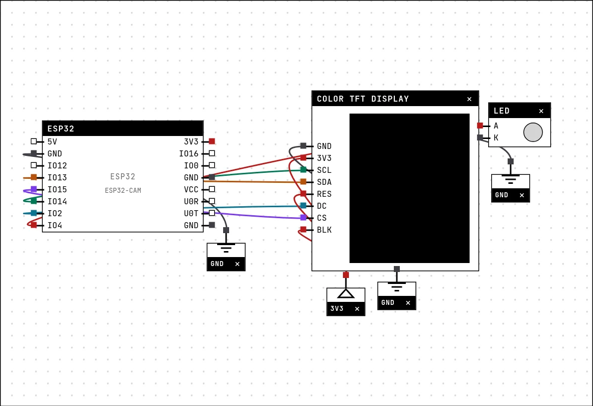
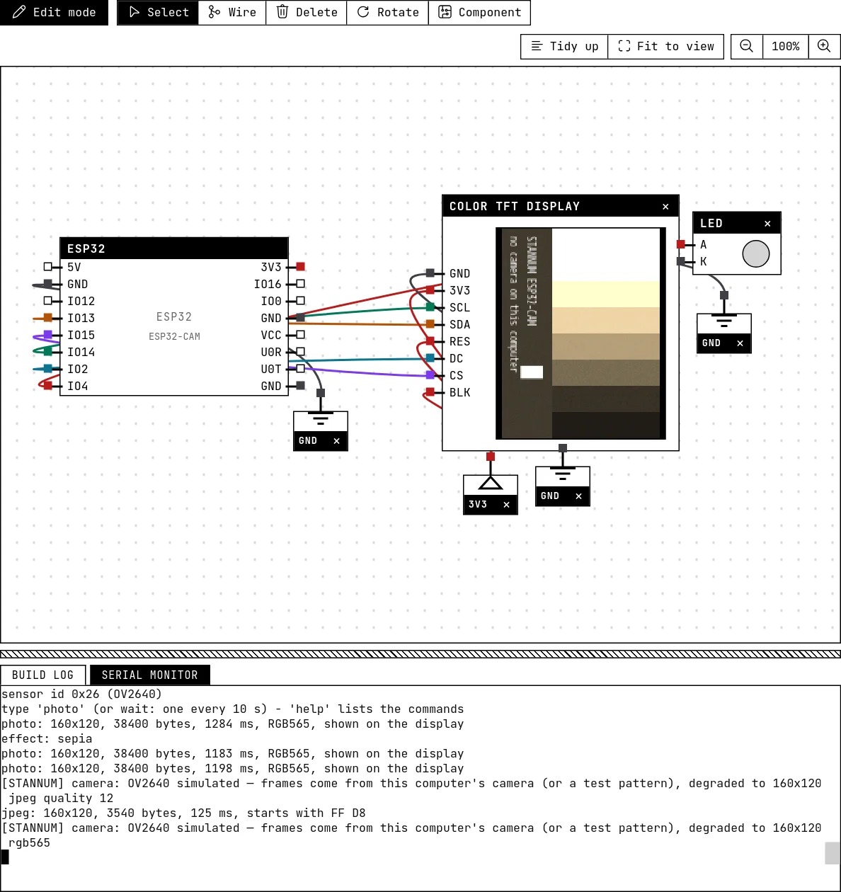
The camera takes most of the board's GPIOs, including 18 and 23 where the default SPI bus lives. The display goes on the pins that are free: SCL on 14, SDA on 13, CS on 15, DC on 2, with RES and BLK on 3V3. The sketch opens the HSPI bus on those pins by name — the same wiring works on the bench.
// ESP32-CAM: photos on a color display
//
// The camera board, programmed like the real one: the same esp_camera API,
// the same AI-Thinker pin map, the same configuration — plus a 1.8" TFT on
// the board's free pins, so you can SEE each frame. The ESP32-CAM has no
// screen of its own: a photo lives in RAM until the code takes it somewhere.
// Here it goes to the display; on a real project it may go to an SD card or
// out over the network instead.
//
// In the simulator the frames come from your computer's camera (or a test
// pattern if there is none), reduced to exactly what the OV2640 delivers.
//
// Type in the serial monitor and press Enter:
//   photo                 one frame, shown on the display
//   live                  live view on/off (frame after frame)
//   jpeg                  one JPEG frame: prints its size — what you would save or send
//   effect none|negative|gray|red|green|blue|sepia
//   mirror | flip         horizontal mirror / vertical flip
//   help
// A photo is also taken by itself every 10 seconds. The flash LED (GPIO 4)
// lights while the sensor is exposing — the LED on the canvas shows it.
//
// THE WIRING (the camera takes most GPIOs; these are the free ones):
//   TFT SCL -> GPIO14    TFT SDA -> GPIO13    TFT CS -> GPIO15    TFT DC -> GPIO2
//   TFT RES -> 3V3 (software reset)    TFT BLK -> 3V3    VCC -> 3V3    GND -> GND
#include <Arduino.h>
#include <SPI.h>
#include <Adafruit_GFX.h>
#include <Adafruit_ST7735.h>
#include "esp_camera.h"

// AI-Thinker ESP32-CAM pin map (camera_pins.h of the CameraWebServer example)
#define PWDN_GPIO_NUM  32
#define RESET_GPIO_NUM -1
#define XCLK_GPIO_NUM   0
#define SIOD_GPIO_NUM  26
#define SIOC_GPIO_NUM  27
#define Y9_GPIO_NUM    35
#define Y8_GPIO_NUM    34
#define Y7_GPIO_NUM    39
#define Y6_GPIO_NUM    36
#define Y5_GPIO_NUM    21
#define Y4_GPIO_NUM    19
#define Y3_GPIO_NUM    18
#define Y2_GPIO_NUM     5
#define VSYNC_GPIO_NUM 25
#define HREF_GPIO_NUM  23
#define PCLK_GPIO_NUM  22

// The display, on the HSPI bus: GPIO 18/23 (the default SPI pins) belong to
// the camera on this board, so the sketch names its own pins.
#define TFT_SCLK 14
#define TFT_MOSI 13
#define TFT_CS   15
#define TFT_DC    2
#define TFT_RST  -1      // RES tied to 3V3: the library resets it by software

SPIClass hspi(HSPI);
Adafruit_ST7735 tft = Adafruit_ST7735(&hspi, TFT_CS, TFT_DC, TFT_RST);

const int FLASH = 4;
String line;
bool live = false;
unsigned long lastAuto = 0;

bool startCamera(pixformat_t format) {
  camera_config_t config = {};
  config.ledc_channel = LEDC_CHANNEL_0;
  config.ledc_timer = LEDC_TIMER_0;
  config.pin_d0 = Y2_GPIO_NUM;  config.pin_d1 = Y3_GPIO_NUM;
  config.pin_d2 = Y4_GPIO_NUM;  config.pin_d3 = Y5_GPIO_NUM;
  config.pin_d4 = Y6_GPIO_NUM;  config.pin_d5 = Y7_GPIO_NUM;
  config.pin_d6 = Y8_GPIO_NUM;  config.pin_d7 = Y9_GPIO_NUM;
  config.pin_xclk = XCLK_GPIO_NUM;
  config.pin_pclk = PCLK_GPIO_NUM;
  config.pin_vsync = VSYNC_GPIO_NUM;
  config.pin_href = HREF_GPIO_NUM;
  config.pin_sccb_sda = SIOD_GPIO_NUM;
  config.pin_sccb_scl = SIOC_GPIO_NUM;
  config.pin_pwdn = PWDN_GPIO_NUM;
  config.pin_reset = RESET_GPIO_NUM;
  config.xclk_freq_hz = 20000000;
  config.pixel_format = format;           // RGB565: pixels the display takes as they are
  config.frame_size = FRAMESIZE_QQVGA;    // 160x120: fits the 160x128 screen and the RAM
  config.jpeg_quality = 12;               // only used by the 'jpeg' command
  config.fb_count = 1;

  esp_err_t err = esp_camera_init(&config);
  if (err != ESP_OK) {
    Serial.printf("camera init failed: 0x%x\n", err);
    return false;
  }
  return true;
}

// One RGB565 frame, straight to the display. The sensor delivers each pixel
// with the HIGH byte first; the library wants the chip's native order — the
// classic swap every ESP32-CAM + TFT project has to do.
bool photo() {
  digitalWrite(FLASH, HIGH);                 // the flash LED, while exposing
  unsigned long t0 = millis();
  camera_fb_t *fb = esp_camera_fb_get();     // waits for the next frame
  digitalWrite(FLASH, LOW);
  if (!fb) {
    Serial.println("capture failed");
    return false;
  }
  uint16_t *px = (uint16_t *)fb->buf;
  for (size_t i = 0; i < fb->len / 2; i++) px[i] = (px[i] << 8) | (px[i] >> 8);
  tft.drawRGBBitmap(0, 4, px, fb->width, fb->height);   // 160x120 in a 160x128 screen
  if (!live)
    Serial.printf("photo: %ux%u, %u bytes, %lu ms, RGB565, shown on the display\n",
                  fb->width, fb->height, fb->len, millis() - t0);
  esp_camera_fb_return(fb);                  // give the buffer back, always
  return true;
}

// A JPEG frame: the format you would write to a card or send over Wi-Fi. The
// driver cannot change format on the fly, so the camera is restarted in JPEG,
// one frame is taken, and it is restarted in RGB565 for the display.
void jpeg() {
  esp_camera_deinit();
  if (!startCamera(PIXFORMAT_JPEG)) return;
  unsigned long t0 = millis();
  camera_fb_t *fb = esp_camera_fb_get();
  if (fb) {
    // a JPEG always starts with the bytes FF D8: a cheap check that it is one
    Serial.printf("jpeg: %ux%u, %u bytes, %lu ms, starts with %02X %02X\n",
                  fb->width, fb->height, fb->len, millis() - t0, fb->buf[0], fb->buf[1]);
    esp_camera_fb_return(fb);
  } else {
    Serial.println("capture failed");
  }
  esp_camera_deinit();
  startCamera(PIXFORMAT_RGB565);
}

void handle(String cmd) {
  cmd.trim();
  cmd.toLowerCase();
  sensor_t *s = esp_camera_sensor_get();
  if (cmd == "photo") {
    photo();
  } else if (cmd == "live") {
    live = !live;
    Serial.println(live ? "live view on - type 'live' again to stop" : "live view off");
  } else if (cmd == "jpeg") {
    jpeg();
  } else if (cmd.startsWith("effect ")) {
    const char *names[] = {"none", "negative", "gray", "red", "green", "blue", "sepia"};
    String v = cmd.substring(7);
    int e = -1;
    for (int i = 0; i < 7; i++) if (v == names[i]) e = i;
    if (e < 0) Serial.println("effects: none negative gray red green blue sepia");
    else { s->set_special_effect(s, e); Serial.printf("effect: %s\n", names[e]); }
  } else if (cmd == "mirror") {
    s->set_hmirror(s, !s->status.hmirror);
    Serial.printf("mirror: %s\n", s->status.hmirror ? "on" : "off");
  } else if (cmd == "flip") {
    s->set_vflip(s, !s->status.vflip);
    Serial.printf("flip: %s\n", s->status.vflip ? "on" : "off");
  } else {
    Serial.println("commands: photo | live | jpeg | effect <none|negative|gray|red|green|blue|sepia> "
                   "| mirror | flip");
  }
}

void setup() {
  Serial.begin(115200);
  pinMode(FLASH, OUTPUT);
  digitalWrite(FLASH, LOW);

  hspi.begin(TFT_SCLK, -1, TFT_MOSI, TFT_CS);   // SCK, MISO (none), MOSI, SS
  tft.initR(INITR_BLACKTAB);                     // the 1.8" 128x160 panel
  tft.setRotation(1);                            // landscape: 160 wide, 128 tall
  tft.fillScreen(ST77XX_BLACK);
  Serial.println("display ready");

  if (!startCamera(PIXFORMAT_RGB565)) return;
  sensor_t *s = esp_camera_sensor_get();
  Serial.printf("sensor id 0x%02x (%s)\n", s->id.PID,
                s->id.PID == OV2640_PID ? "OV2640" : "unknown");
  Serial.println("type 'photo' (or wait: one every 10 s) - 'help' lists the commands");
}

void loop() {
  while (Serial.available()) {
    char c = Serial.read();
    if (c == '\r' || c == '\n') {
      if (line.length()) handle(line);
      line = "";
    } else if (line.length() < 40) {
      line += c;
    }
  }
  if (live) {
    photo();                                   // frame after frame, as fast as they come
  } else if (millis() - lastAuto > 10000) {
    lastAuto = millis();
    photo();
  }
}Run it
Press Build and run. The browser asks for the camera (allow it, or watch the test pattern). A frame appears on the display every 10 seconds. Then, in the serial monitor:
| Type | What happens |
|---|---|
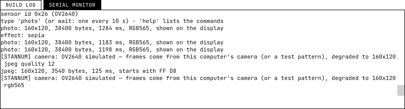
photo | One frame on the display. The monitor prints its size in pixels and bytes and the time it took. The LED flashes while the sensor exposes. |
live | Frame after frame, as fast as they come — a live view on the display. Type it again to stop. |
jpeg | One frame as JPEG: the format you would save to a card or send over the network. The monitor prints the byte count and the first two bytes — FF D8. The camera restarts in RGB565 afterwards. |
effect gray, effect negative, effect sepia | The sensor's special effects, applied before the frame leaves the sensor — as on the chip. The next frame on the display shows them. |
mirror, flip | The two axes of the sensor. Boards mounted upside down need flip. |
What is — and is not — modeled
- Resolution and format are exact: the frame has the configured size, and it is RGB565/grayscale pixels or a JPEG at the configured quality, so a sketch that draws, measures, stores or sends photos behaves like the board. The look — softness, grain, the color of the effects — is an approximation of a small sensor, not a measurement of an OV2640.
- Timing: a frame arrives in 150 to 500 ms whatever the size. A real OV2640 is faster at small sizes (tens of milliseconds at QQVGA) and about this slow at UXGA. Drawing on the display is slower here than on the board.
- Not simulated: the SCCB register access (
get_reg/set_regdo nothing), exposure and gain control (the browser's camera does its own), the on-board SD slot (it uses the SD_MMC bus, which the lab does not emulate — the SPI SD card module works), and the CameraWebServer's video stream reached from outside: the firmware's network is private to the simulation. - The pins with an owner: the camera keeps 15 GPIOs off the header, so you cannot wire them by mistake. Of the ones on the header, GPIO 0 is the camera's clock and GPIO 16 the PSRAM's chip select: wire anything there and the lab shows an error, because on the real board the camera stops. GPIO 1 and 3 are the programming serial lines, and get a warning. GPIOs 2, 4, 12 to 15 are shared with the SD slot: free to use as long as the code does not use the card.
- Privacy: the image goes only to your simulation session; the camera light goes off when the simulation stops.
Try this
- Wire an SPI SD card module (see its guide) and save each
jpegas/photoN.jpg— the file is a real JPEG you could open on a computer. - Take a photo when the PIR sensor detects motion — the classic trail camera, with the display showing what it caught.
- Switch to
PIXFORMAT_GRAYSCALEand compute the average brightness of the frame fromfb->buf: a light meter, printed on the display.
See also
- ESP32 boards — Eight boards to choose from, pin by pin: which GPIOs reach the header, which are input-only, which have an ADC, and which must be left alone.
- Color TFT display (ST7735 / ST7789) — The 7-pin SPI color screen in five sizes, from 80×160 to 240×320, with the quirks of the real controller — including the white screen of a wrong init.
- The serial monitor — Reading what the firmware prints, typing to the board, and an example that takes commands from the monitor.
- SD card — A micro SD module on SPI that stores real files — they survive a restart, and you can eject the card to test your error handling.