Tutorials / Output
SG90 servo
A 9 g micro servo whose arm follows the width of the pulse it receives — the block shows the pulse it measures.
- Potentiometer
- SG90 servo
What it is
A hobby servo does not receive “degrees”: it receives a pulse every 20 ms, and the width of that pulse — about 0.5 to 2.4 ms — sets the arm's angle. servo.write(90) only translates degrees into a pulse width; the electronics inside the servo do the rest.
In the simulator
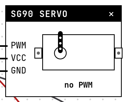
The block is the servo seen from above, with its cross-shaped arm. The arm turns to the angle that corresponds to the pulse the firmware is generating, and the reading below it shows the measured pulse in microseconds next to the angle — “no PWM” means the pin carries no pulse train yet. Two settings calibrate it: the pulse for 0° and the pulse for 180°, 544 and 2400 µs by default, which are the defaults of the Arduino library.
Pins
| Pin | What it is |
|---|---|
| PWM | PWM signal — to a GPIO |
| VCC | power — to a 3V3 symbol (on a bench the SG90 wants 5 V from a proper supply) |
| GND | ground — to a GND symbol |
Wiring
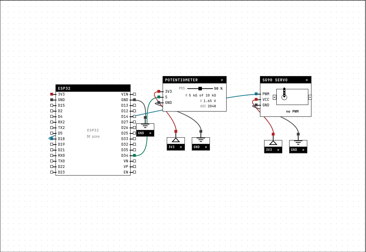
The circuit below is the example Servo on a potentiometer from the lab — open it with Project → Open example… and it comes ready to run.
| SG90 servo pin | Goes to |
|---|---|
| PWM | D18 on the board (GPIO 18) |
| VCC | a 3V3 symbol |
| GND | a GND symbol |
Settings
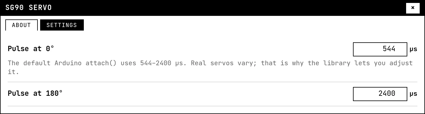
Double-click the block's title bar to open its card, then the Settings tab. Changes apply to the running simulation right away.
| Setting | Accepts | Default | Notes |
|---|---|---|---|
| Pulse at 0° | 400 to 1500 µs | 544 µs | The default Arduino attach() uses 544–2400 µs. Real servos vary; that is why the library lets you adjust it. |
| Pulse at 180° | 1500 to 3000 µs | 2400 µs |
Code
#include <Arduino.h>
#include <ESP32Servo.h>

// The servo does not receive "degrees": it receives a PULSE of ~0.5 to 2.4 ms
// every 20 ms. write(angulo) only translates — the part shows the pulse measured.
Servo servo;
const int POT = 34, SINAL = 18;

void setup() {
  Serial.begin(115200);
  servo.attach(SINAL);
}

void loop() {
  int leitura = analogRead(POT);              // 0..4095
  int angulo = map(leitura, 0, 4095, 0, 180);
  servo.write(angulo);
  Serial.printf("pot=%4d -> %3d degrees\n", leitura, angulo);
  delay(100);
}The example uses the ESP32Servo library: attach(pin) sets up the PWM channel, write(angle) moves. The potentiometer reading is mapped to 0–180°. Without a library, ledcAttach and ledcWrite at 50 Hz produce the same signal.
Run it
Press Build and run. The first build of a project takes a while; after that, only what changed is rebuilt.
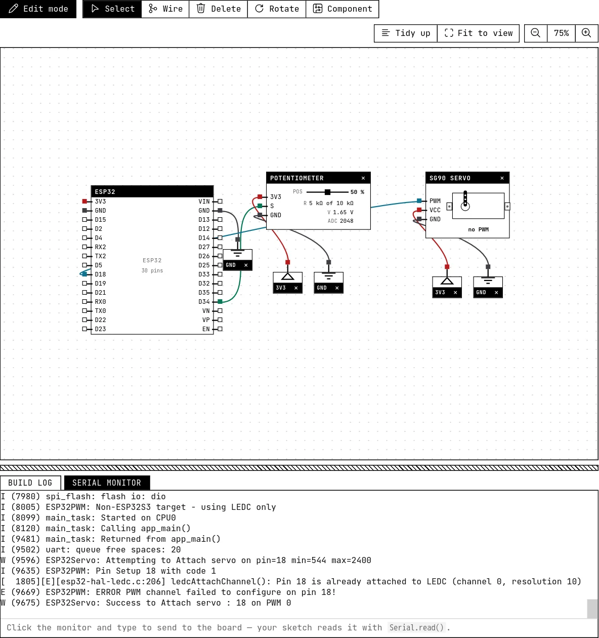
Drag the potentiometer from 0 to 100 %: the arm sweeps from 0° to 180°, and the reading shows the pulse going from about 544 to 2400 µs. The serial monitor prints the angle.
How the simulation models it
- The simulation watches the chip's PWM peripheral and reports frequency and duty of every channel that drives a GPIO. The servo block converts duty into pulse width (duty ÷ frequency) and pulse width into angle, using the two calibration settings.
- A pin driven with plain
digitalWriteis not a pulse train: the arm sits at 0° and the reading says “no PWM”. - Pulses outside the 0°–180° window are clamped to the ends, like a real servo hitting its stops.
Try this
- Sweep the arm back and forth by itself, one degree every 15 ms, with no potentiometer.
- Change the 0° pulse to 1000 µs in Settings and see how
write(0)now lands somewhere else — this is what calibrating a real servo looks like.
See also
- Potentiometer — A variable resistor whose wiper divides 3.3 V — the first analog input, read with analogRead().
- LED — The first output of every project: a GPIO set HIGH lights it, LOW turns it off.