Tutorials / Sensors
LDR (photoresistor)
A resistor that drops with light — read through the ADC as a number that grows with brightness.
- LDR
- LED
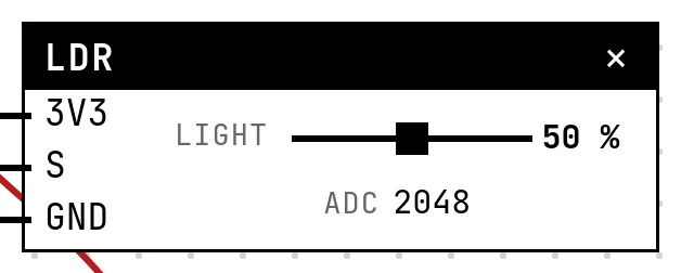
What it is
A light-dependent resistor has a few hundred ohms in daylight and a megohm in the dark. On its own a resistance is not something a GPIO can read, so the module puts it in a voltage divider with a fixed resistor: the midpoint's voltage changes with the light, and the ADC reads that.
In the simulator
The block has a Light slider, 0 % (total darkness) to 100 %, and shows the ADC count the code will read. More light, higher reading — the usual orientation of the divider.
Pins
| Pin | What it is |
|---|---|
| 3V3 | one end of the divider — to a 3V3 symbol |
| S | the divider's midpoint — to a GPIO with an ADC |
| GND | the other end — to a GND symbol |
Wiring
The circuit below is the example Automatic lamp with an LDR from the lab — open it with Project → Open example… and it comes ready to run.
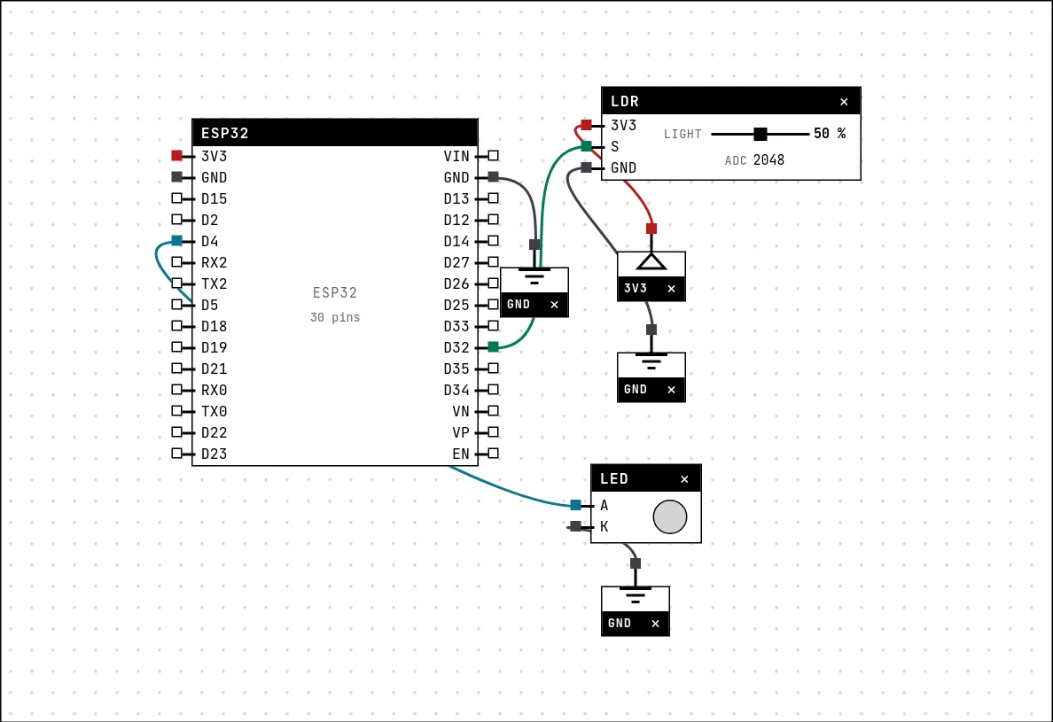
| LDR pin | Goes to |
|---|---|
| 3V3 | a 3V3 symbol |
| S | D32 on the board (GPIO 32) |
| GND | a GND symbol |
Code
#include <Arduino.h>

const int LDR = 32;    // the MORE light, the HIGHER the reading
const int LAMPADA = 4;
const int LIMIAR = 1500;

void setup() {
  Serial.begin(115200);
  pinMode(LAMPADA, OUTPUT);
}

void loop() {
  int luz = analogRead(LDR);
  bool escuro = luz < LIMIAR;
  digitalWrite(LAMPADA, escuro ? HIGH : LOW);
  Serial.printf("light=%d (%s)\n", luz, escuro ? "on" : "off");
  delay(200);
}analogRead(LDR), a threshold (1500 in the example) and digitalWrite on the lamp's pin. The reading is printed with the decision on every pass.
Run it
Press Build and run. The first build of a project takes a while; after that, only what changed is rebuilt.
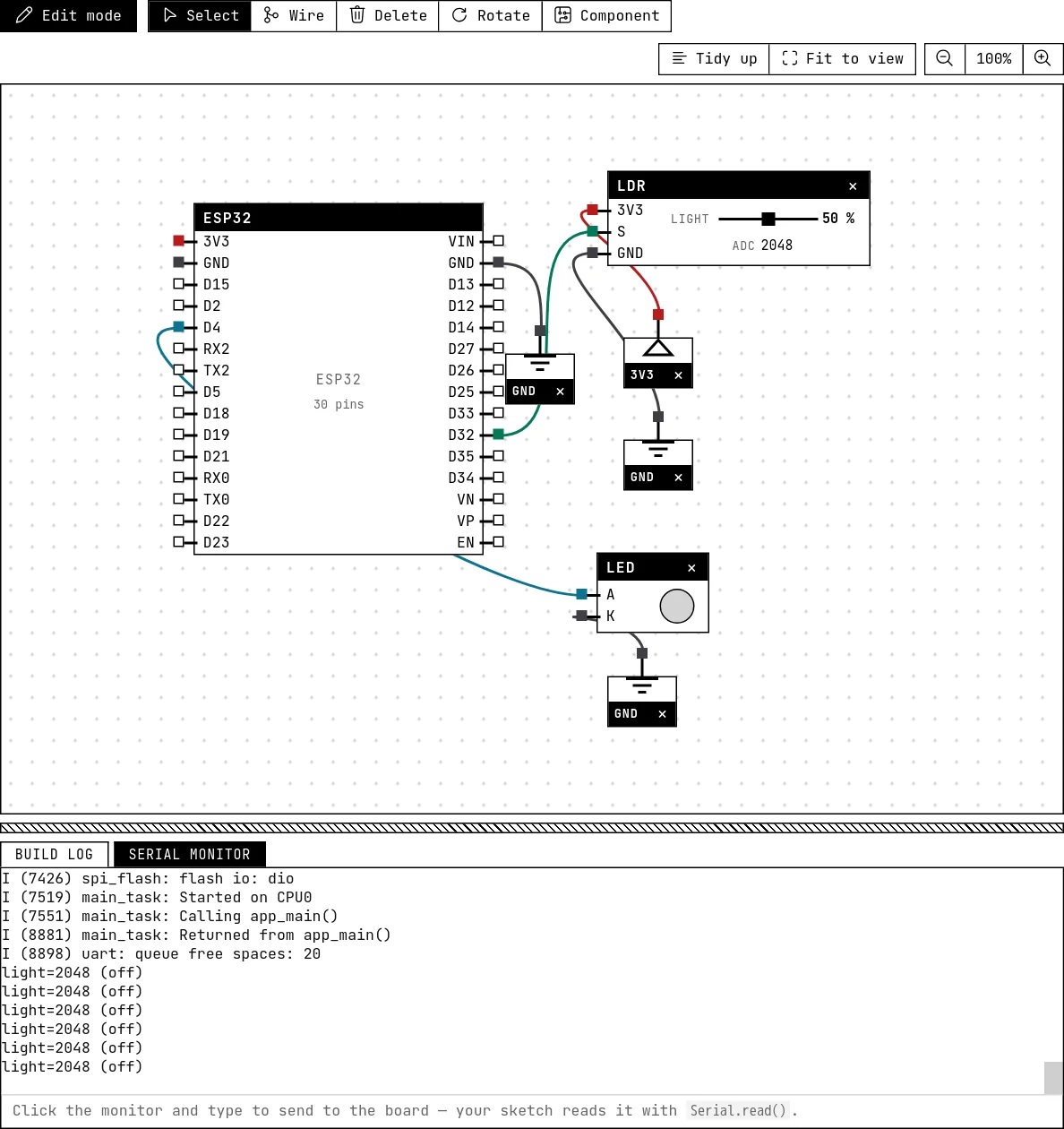
Drag the light slider down: below the threshold the LED lights — the automatic lamp. The serial monitor prints the reading and “on”/“off”.
How the simulation models it
- The reading is linear with the slider: 0 % gives 0, 100 % gives 4095. A real LDR is far from linear (its resistance follows a power law of the light), and the divider bends the curve again; the simulation keeps the exercise about thresholds, not about the curve.
- The value is sent whenever the slider moves and at start-up.
Try this
- Add hysteresis: turn on below 1400 and off above 1600, so the lamp does not flicker around the threshold.
- Print the reading as a percentage of brightness.
See also
- Potentiometer — A variable resistor whose wiper divides 3.3 V — the first analog input, read with analogRead().
- LM35 temperature sensor — Ten millivolts per degree, straight from the sensor: read the voltage, multiply by 100.
- Soil moisture and rain sensors — Two resistive boards with the same electronics: a dry board reads HIGH, and a comparator gives a digital alarm.