Tutorials / Sensors
NTC thermistor
A resistor that shrinks as it heats — cheaper than the LM35, but the code has to undo a curve.
- NTC 10k
What it is
An NTC thermistor is a resistor with a negative temperature coefficient: 10 kΩ at 25 °C, about 3.6 kΩ at 50 °C, roughly 30 kΩ at 0 °C. The module puts it in a divider with a fixed resistor. Reading it takes two steps: from the ADC count back to the thermistor's resistance, and from the resistance to a temperature with the Beta equation.
In the simulator
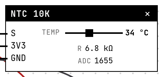
The block has a Temp slider (−10 to 100 °C) and shows the thermistor's resistance and the ADC count. Two settings come from the datasheet of the part: the resistance at 25 °C (2.2 kΩ, 10 kΩ or 100 kΩ) and the Beta coefficient (3950 K by default).
Pins
| Pin | What it is |
|---|---|
| S | the divider's midpoint — to a GPIO with an ADC |
| 3V3 | the fixed resistor's end — to a 3V3 symbol |
| GND | the thermistor's end — to a GND symbol |
Wiring
Build this circuit yourself: start a New project, add the parts from the catalog and wire them as in the table.
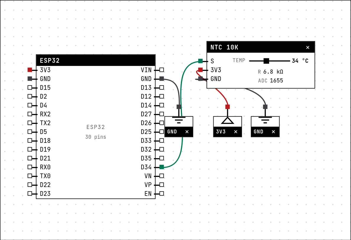
| NTC 10k pin | Goes to |
|---|---|
| S | D34 on the board (GPIO 34) |
| 3V3 | a 3V3 symbol |
| GND | a GND symbol |
Settings
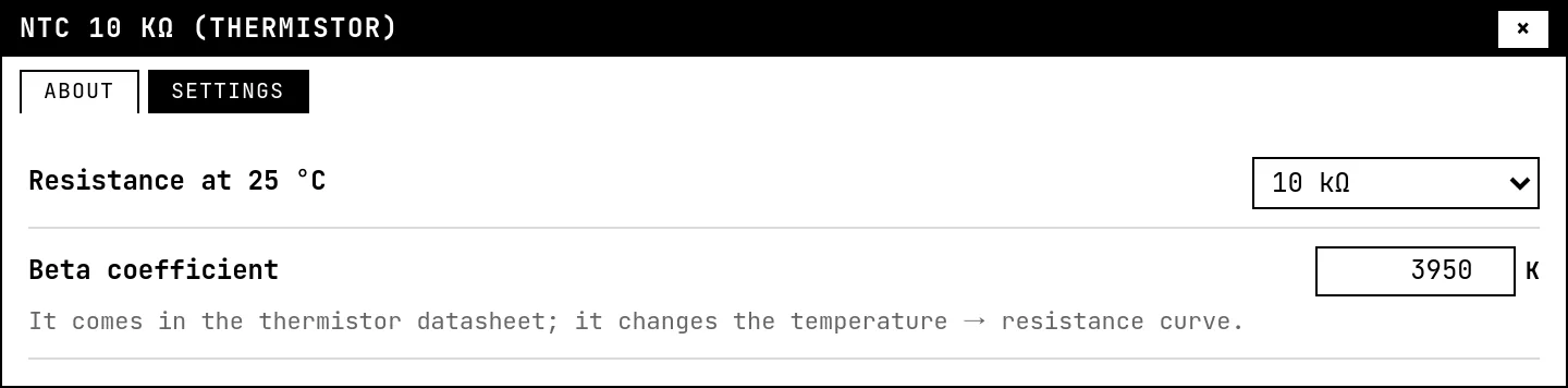
Double-click the block's title bar to open its card, then the Settings tab. Changes apply to the running simulation right away.
| Setting | Accepts | Default | Notes |
|---|---|---|---|
| Resistance at 25 °C | 2.2 kΩ · 10 kΩ · 100 kΩ | 10 kΩ | |
| Beta coefficient | 2000 to 5000 K | 3950 K | It comes in the thermistor datasheet; it changes the temperature → resistance curve. |
Code
#include <Arduino.h>

// The NTC is a resistor that shrinks as it heats up. On the module it sits in
// a voltage divider with a fixed resistor, so what the ADC sees is a voltage —
// and the code has to walk back from that voltage to a temperature.
const int NTC = 34;
const float R_FIXED = 10000.0;   // the other half of the divider
const float R25 = 10000.0;       // NTC resistance at 25 C
const float BETA = 3950.0;       // from the thermistor datasheet

void setup() {
  Serial.begin(115200);
}

void loop() {
  int raw = analogRead(NTC);                          // 0..4095
  if (raw <= 0 || raw >= 4095) { delay(500); return; }  // open or shorted

  // divider: the NTC is on the GND side, the fixed resistor on the 3V3 side
  float rNtc = R_FIXED * raw / (4095.0 - raw);

  // Steinhart-Hart, simplified to the Beta equation
  float kelvin = 1.0 / (1.0 / 298.15 + log(rNtc / R25) / BETA);
  float celsius = kelvin - 273.15;

  Serial.printf("ADC=%4d  R=%6.0f ohm  T=%.1f C\n", raw, rNtc, celsius);
  delay(500);
}
First the divider, inverted: the thermistor is on the GND side, so R = R_FIXED × raw ÷ (4095 − raw). Then the Beta equation, 1/T = 1/298.15 + ln(R/R25)/B, in kelvin. The sketch prints the count, the resistance and the temperature so you can check each step against the block.
Run it
Press Build and run. The first build of a project takes a while; after that, only what changed is rebuilt.
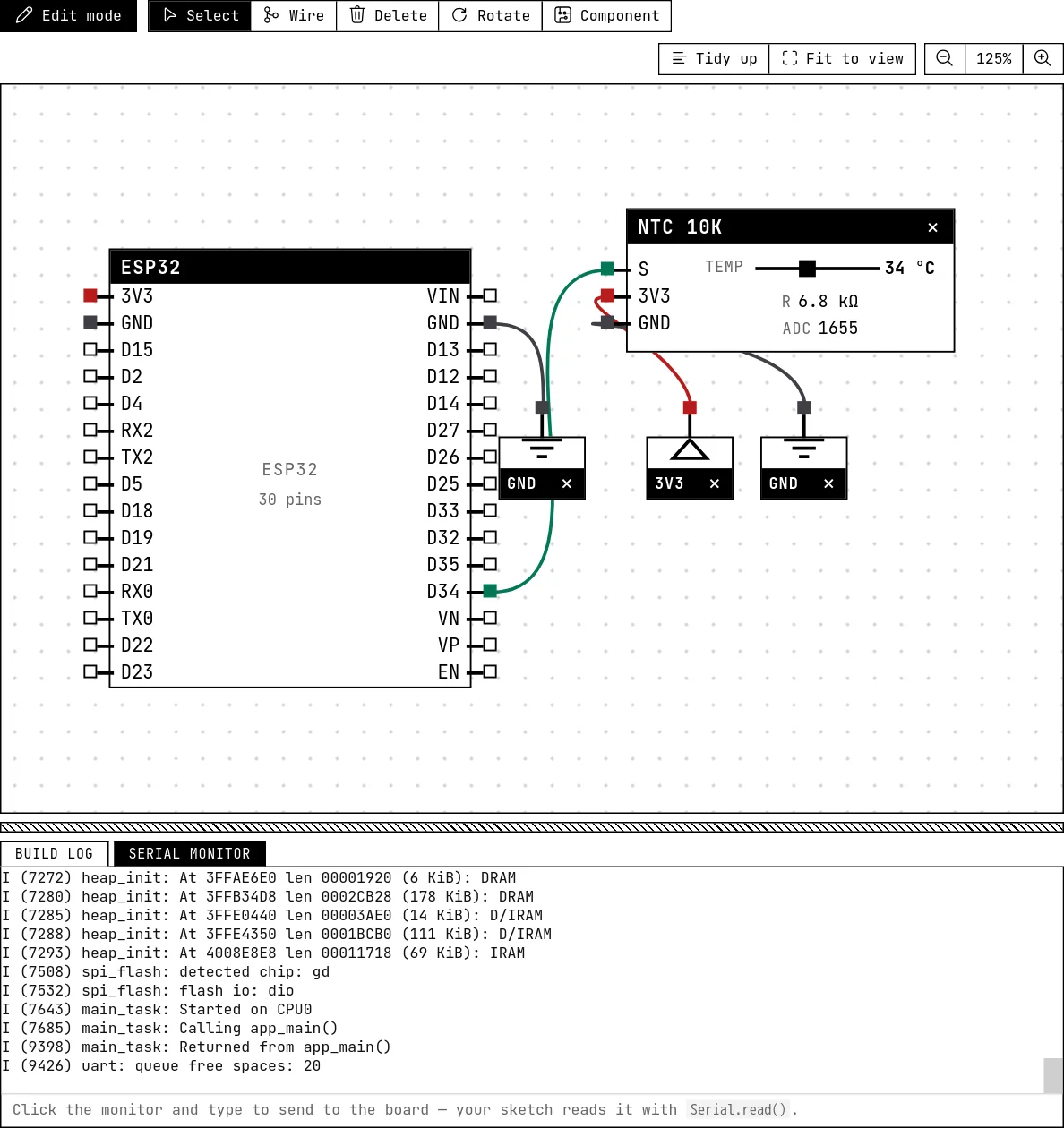
Drag the slider and compare the serial monitor with the block: the resistance and the temperature the code computes match the ones the block shows.
How the simulation models it
- The resistance follows the Beta equation with the R25 and Beta from Settings; the ADC count is
4095 × R ÷ (R + R25)— the fixed resistor of the divider equals R25, which is how the common modules are built. - Change Beta in Settings without changing the code and the readings drift: that is the calibration error you get from using a datasheet value for a different part.
Try this
- Set R25 to 100 kΩ in Settings and adjust the code's constants to match.
- Compare with the LM35 guide: same temperature, very different counts. Which one uses the ADC range better around room temperature?
See also
- LM35 temperature sensor — Ten millivolts per degree, straight from the sensor: read the voltage, multiply by 100.
- Potentiometer — A variable resistor whose wiper divides 3.3 V — the first analog input, read with analogRead().