Tutorials / Sensors
MPU6050 accelerometer and gyroscope
Six axes on I²C: at rest the accelerometer measures gravity, and tilting redistributes it — that is how a phone knows it was turned.
- MPU6050
- LED
- Active buzzer
What it is
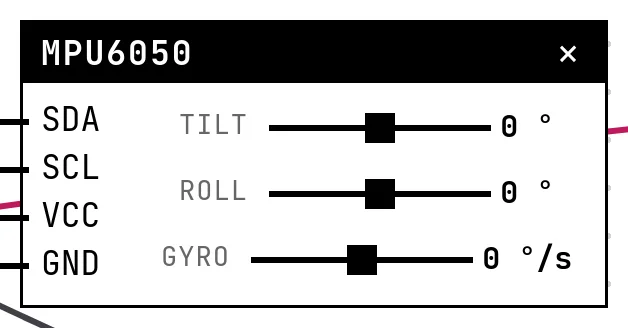
The MPU6050 packs a 3-axis accelerometer and a 3-axis gyroscope. Standing still, the accelerometer reads 1 g straight down; tilt the board and that 1 g spreads across the axes, so atan2 of two axes gives the angle. The gyroscope reports how fast the board turns. Address 0x68, or 0x69 with the AD0 pin high.
In the simulator
The block has three sliders: Tilt (pitch, front/back), Roll (side) and Gyro (turn rate around the vertical axis). The address is in Settings.
Pins
| Pin | What it is |
|---|---|
| SDA | I²C data — to a GPIO |
| SCL | I²C clock — to a GPIO |
| VCC | power — to a 3V3 symbol |
| GND | ground — to a GND symbol |
Wiring
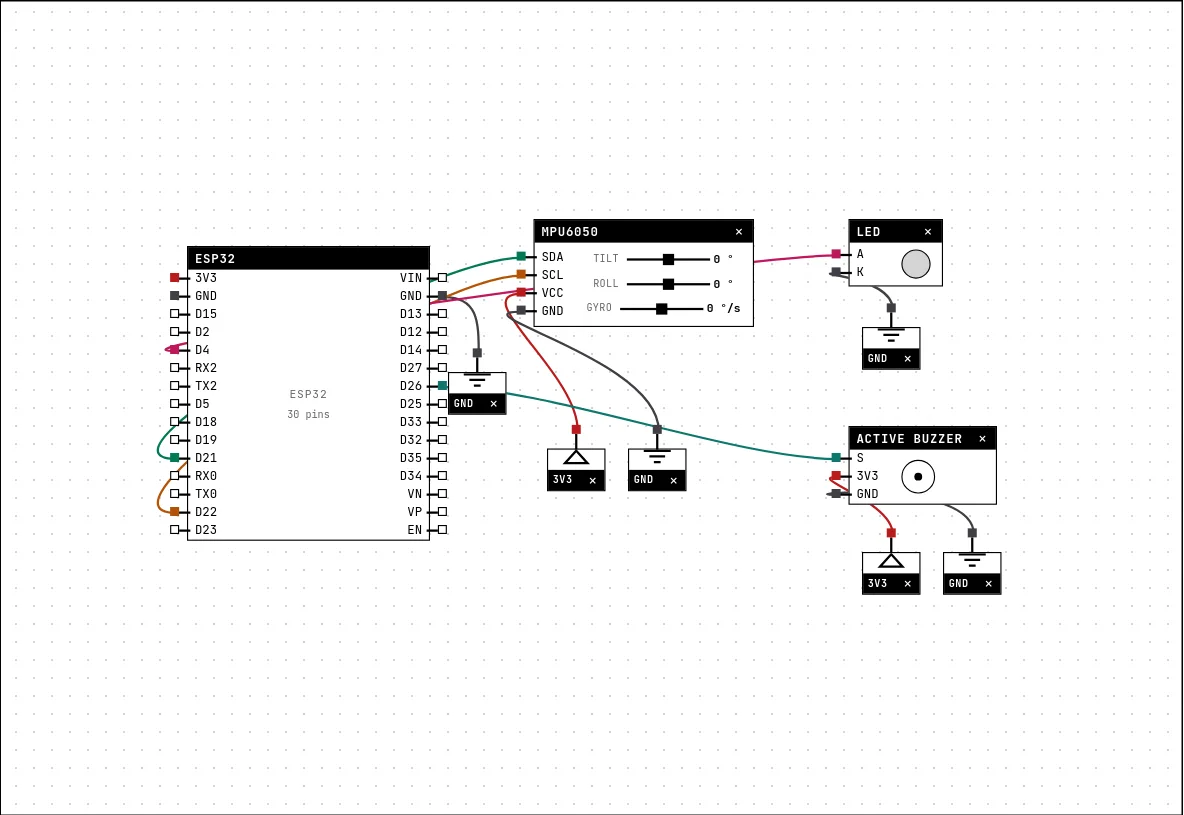
The circuit below is the example Bubble level — MPU6050 from the lab — open it with Project → Open example… and it comes ready to run.
| MPU6050 pin | Goes to |
|---|---|
| SDA | D21 on the board (GPIO 21) |
| SCL | D22 on the board (GPIO 22) |
| VCC | a 3V3 symbol |
| GND | a GND symbol |
Settings
Double-click the block's title bar to open its card, then the Settings tab. Changes apply to the running simulation right away.

| Setting | Accepts | Default | Notes |
|---|---|---|---|
| I²C address | 0x68 (AD0 to GND) · 0x69 (AD0 to VCC) | 0x68 (AD0 to GND) | The AD0 pin on the little board picks between the two. |
Code
#include <Arduino.h>
#include <Adafruit_MPU6050.h>
#include <Adafruit_Sensor.h>
#include <Wire.h>

// At rest, the accelerometer measures GRAVITY. Tilting spreads that 1 g across
// the axes — and atan2 recovers the angle. This is how a phone knows it was
// turned sideways.
Adafruit_MPU6050 mpu;
const int LED = 4, BUZZER = 26;

void setup() {
  Serial.begin(115200);
  delay(300);
  Wire.begin(21, 22);
  pinMode(LED, OUTPUT);
  pinMode(BUZZER, OUTPUT);
  if (!mpu.begin()) {
    Serial.println("MPU6050 not found — check SDA and SCL");
    for (;;) delay(1000);
  }
}

void loop() {
  sensors_event_t a, g, t;
  mpu.getEvent(&a, &g, &t);

  float pitch = atan2(-a.acceleration.x, a.acceleration.z) * 180.0 / PI;
  float roll  = atan2(a.acceleration.y, a.acceleration.z) * 180.0 / PI;

  bool nivelado = fabs(pitch) < 3 && fabs(roll) < 3;
  bool demais   = fabs(pitch) > 25 || fabs(roll) > 25;
  digitalWrite(LED, nivelado);
  digitalWrite(BUZZER, demais);

  Serial.printf("pitch=%+6.1f roll=%+6.1f %s\n", pitch, roll,
                nivelado ? "LEVEL" : demais ? "tilted TOO FAR" : "");
  delay(400);
}The Adafruit MPU6050 library: mpu.begin(), then getEvent() fills acceleration, rotation and temperature. The example computes pitch and roll with atan2 and decides between “LEVEL” (both within 3°), tilted, and “too far” (past 25°), driving an LED and a buzzer.
Run it
Press Build and run. The first build of a project takes a while; after that, only what changed is rebuilt.
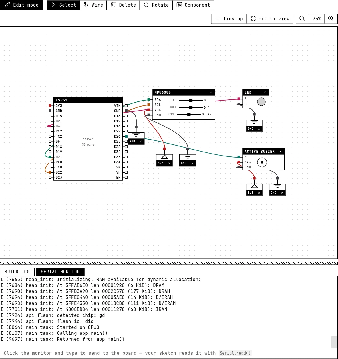
With the sliders at zero the LED is on (level). Drag Tilt past 25° and the buzzer sounds. The serial monitor prints pitch and roll with one decimal.
How the simulation models it
- Acceleration is computed from the two tilt angles as the components of 1 g, in the ±2 g scale the library configures (16384 counts per g); the Z gyroscope comes from the slider in the ±500 °/s scale; X and Y rotation are zero. The chip's temperature reads a fixed 25 °C.
- The registers the library needs are there: WHO_AM_I, the power register with its self-clearing reset bit, the data block. A sketch that changes the scale in the code will read with the corresponding factor.
- No vibration, no drift: the gyroscope's famous bias does not exist here.
Try this
- Show pitch and roll as a bubble on the OLED display — a real spirit level.
- Integrate the gyroscope's Z rate over time to estimate heading, and see it grow without bound when the slider is not at zero.
See also
- Magnetometer (HMC5883L compass) — Three magnetic axes on I²C; atan2 of X and Y is the heading — the electronic compass, without a library.
- BME280 environmental sensor — Temperature, pressure and humidity from one I²C chip, read by the real Adafruit library — calibration and all.
- OLED display (SSD1306) — The 0.96″ 128×64 screen on I²C: two wires, an address, and a library that draws text and shapes.