Tutorials / Output
LED
The first output of every project: a GPIO set HIGH lights it, LOW turns it off.
- LED
- Button
- Potentiometer
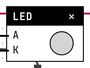
What it is
A light-emitting diode lights when current flows from its anode to its cathode. On a bench it needs a series resistor (220 to 330 Ω for a 3.3 V GPIO) so the current stays around 10 mA; forget it and the LED, or the pin, goes first.
In the simulator
The block has the two legs and a dome that lights in the color chosen on its card. It follows the level of the GPIO wired to A: HIGH is on, LOW is off, in real time — a delay(500) in the code is half a second on the screen.
Pins
| Pin | What it is |
|---|---|
| A | anode (+), the long leg — wire it to the GPIO that drives the LED |
| K | cathode (−), the short leg — wire it to a GND symbol |
Wiring
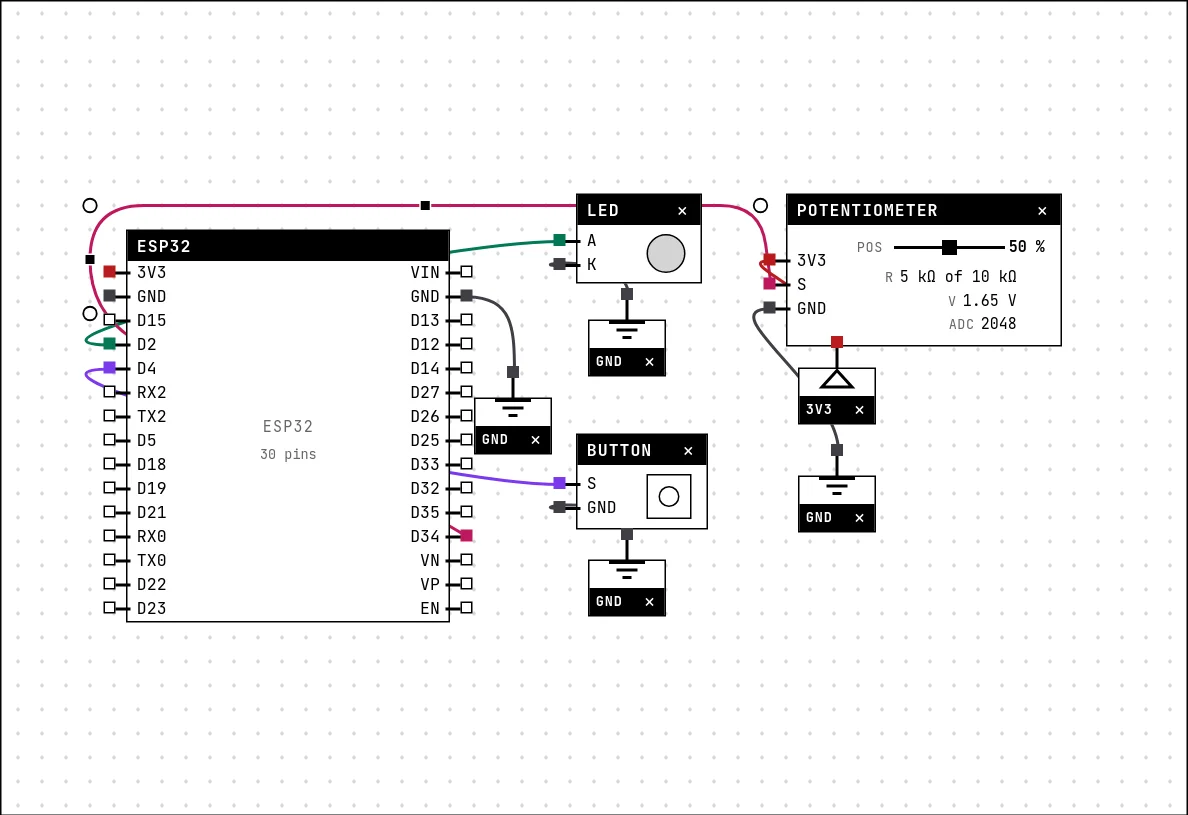
The circuit below is the example Blink with button and potentiometer from the lab — open it with Project → Open example… and it comes ready to run.
| LED pin | Goes to |
|---|---|
| A | D2 on the board (GPIO 2) |
| K | a GND symbol |
Settings
Double-click the block's title bar to open its card, then the Settings tab. Changes apply to the running simulation right away.

| Setting | Accepts | Default | Notes |
|---|---|---|---|
| Color | Red · Green · Blue · Yellow · Orange · White | Red | Only the package: the GPIO does not know the color. |
Code
#include <Arduino.h>

const int LED = 2;
const int BOTAO = 4;
const int POT = 34;

void setup() {
  Serial.begin(115200);
  pinMode(LED, OUTPUT);
  pinMode(BOTAO, INPUT_PULLUP);
  Serial.println("ready");
}

void loop() {
  // the potentiometer sets the blink speed
  int leitura = analogRead(POT);
  int intervalo = map(leitura, 0, 4095, 60, 1000);

  // while the button is held down the LED stays on
  if (digitalRead(BOTAO) == LOW) {
    digitalWrite(LED, HIGH);
    delay(100);
    return;
  }

  digitalWrite(LED, HIGH);
  delay(intervalo);
  digitalWrite(LED, LOW);
  delay(intervalo);
  Serial.printf("pot=%d interval=%d\n", leitura, intervalo);
}
Three parts work together in this example: the LED on GPIO 2, a button on GPIO 4 and a potentiometer on GPIO 34. pinMode(LED, OUTPUT) makes the pin an output; digitalWrite(LED, HIGH) and LOW do the rest. The potentiometer reading sets the blink interval, and holding the button keeps the LED on — the Button and Potentiometer guides cover those two.
Run it
Press Build and run. The first build of a project takes a while; after that, only what changed is rebuilt.
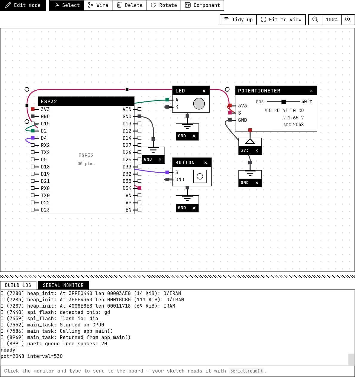
The LED blinks at the speed set by the potentiometer. Drag the potentiometer's slider and the blink changes; hold the button on the canvas and the LED stays on. The serial monitor prints the reading and the interval on every cycle.
How the simulation models it
- The LED is on when the GPIO wired to A reads HIGH, at the instant the firmware changes it. The lab does not check that K reaches ground — wire it anyway: the drawing is the circuit you will build.
- Brightness is not modeled. Driving the pin with PWM (
ledcWrite,analogWrite) makes the LED follow the fast on/off of the signal; it will look on, not dim. - The Color setting changes only the glass of the dome. The GPIO knows nothing about color.
Try this
- Add a second LED on GPIO 15 and make the two alternate: one on while the other is off.
- Replace the two
delay()calls by amillis()comparison, so the loop keeps reading the button while the LED is off. - Wire the LED to GPIO 34 and build. Read what the compiler and the serial monitor say — 34 is input only.
See also
- Your first circuit: blink an LED — From an empty canvas to a blinking LED — placing a part, drawing wires, writing the code, saving and running. Ten minutes, and you will have used every part of the lab once.
- RGB LED — Three LEDs in one package, one GPIO each — red, green and blue mix into eight colors.
- LED bar — A row of 2 to 16 LEDs, one GPIO each — the level meter of every stereo.