Tutorials / Input
4×4 matrix keypad
Sixteen keys on eight wires: the code scans rows and columns, and the simulation closes the right crossing.
- Keypad 4×4
- LED
- Active buzzer
What it is
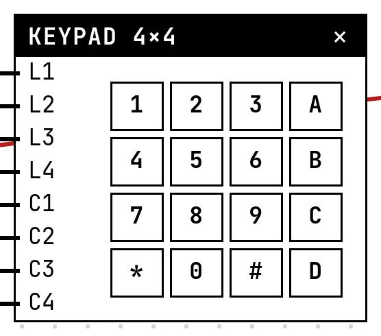
A membrane keypad has no electronics: each key connects one row wire to one column wire. To read it the firmware scans — drives one line, reads the others, moves on — and the crossing that reads LOW is the key. The Keypad library does this for you and adds debouncing.
In the simulator
The block is the keypad; press and hold a key with the mouse. The simulation joins the row and the column of every pressed key at the pin level, so whichever way the code scans — the library drives the columns and reads the rows, hand-written code often does the opposite — the reading is right.
Pins
| Pin | What it is |
|---|---|
| L1 | row 1 — to a GPIO |
| L2 | row 2 — to a GPIO |
| L3 | row 3 — to a GPIO |
| L4 | row 4 — to a GPIO |
| C1 | column 1 — to a GPIO |
| C2 | column 2 — to a GPIO |
| C3 | column 3 — to a GPIO |
| C4 | column 4 — to a GPIO |
Wiring
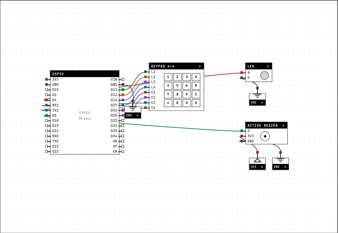
The circuit below is the example Password lock — 4×4 keypad from the lab — open it with Project → Open example… and it comes ready to run.
| Keypad 4×4 pin | Goes to |
|---|---|
| L1 | D13 on the board (GPIO 13) |
| L2 | D12 on the board (GPIO 12) |
| L3 | D14 on the board (GPIO 14) |
| L4 | D27 on the board (GPIO 27) |
| C1 | D26 on the board (GPIO 26) |
| C2 | D25 on the board (GPIO 25) |
| C3 | TX2 on the board (GPIO 17) |
| C4 | RX2 on the board (GPIO 16) |
Code
#include <Arduino.h>
#include <Keypad.h>

char teclas[4][4] = {
  {'1','2','3','A'}, {'4','5','6','B'}, {'7','8','9','C'}, {'*','0','#','D'}};
byte pinosLinha[4]  = {13, 12, 14, 27};
byte pinosColuna[4] = {26, 25, 17, 16};
Keypad teclado(makeKeymap(teclas), pinosLinha, pinosColuna, 4, 4);

const String SENHA = "1234";
const int LED = 4, BUZZER = 5;
String digitado = "";

void setup() {
  Serial.begin(115200);
  pinMode(LED, OUTPUT);
  pinMode(BUZZER, OUTPUT);
  Serial.println("type the password then #  (* clears)");
}

void loop() {
  char k = teclado.getKey();
  if (!k) return;

  if (k == '*') {
    digitado = "";
    Serial.println("cleared");
  } else if (k == '#') {
    if (digitado == SENHA) {
      Serial.println(">>> OPEN <<<");
      digitalWrite(LED, HIGH);
      delay(3000);
      digitalWrite(LED, LOW);
    } else {
      Serial.println("wrong password!");
      digitalWrite(BUZZER, HIGH);
      delay(400);
      digitalWrite(BUZZER, LOW);
    }
    digitado = "";
  } else {
    digitado += k;
    Serial.printf("* (%d digits)\n", digitado.length());
  }
}The key map, the two arrays of pins and the Keypad object. getKey() returns the key pressed since the last call, or nothing. The example collects digits, compares with the password on #, clears on *, and answers with the LED or the buzzer.
Run it
Press Build and run. The first build of a project takes a while; after that, only what changed is rebuilt.
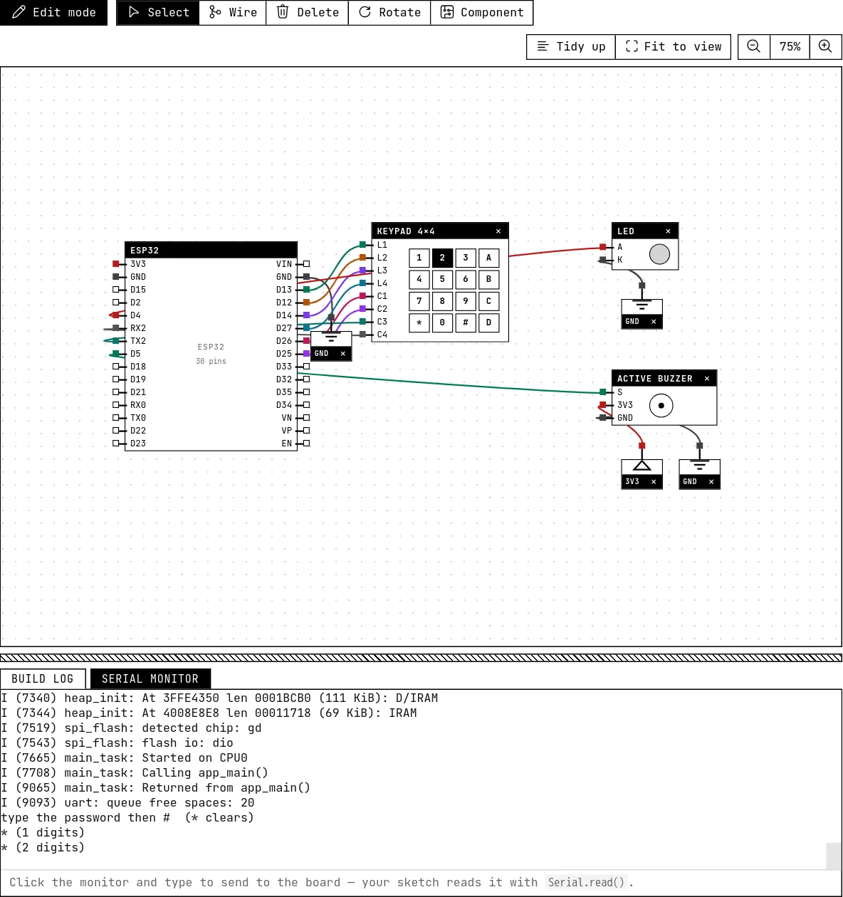
Press 1, 2, 3, 4 and then #: the serial monitor says “OPEN” and the green LED lights for three seconds. A wrong code sounds the buzzer. Each digit prints a “*” with the count.
How the simulation models it
- The coupling is direction-agnostic: whichever of the two lines the firmware configured as an output drives, and the line configured as an input follows (LOW if a pressed key connects it to a line driven LOW, otherwise HIGH as if pulled up).
- Several keys held at once are all coupled — ghosting, as on the real matrix without diodes.
- No bounce; the library's debounce is not exercised.
Try this
- Change the password and make it 6 digits.
- Lock out for 10 seconds after three wrong attempts.
See also
- Push button — A momentary contact: HIGH while released, LOW while pressed — the first digital input.
- Active buzzer — A beeper with its own fixed tone: HIGH sounds it, LOW silences it — and it really sounds in your browser.
- LED — The first output of every project: a GPIO set HIGH lights it, LOW turns it off.