Tutorials / Output
OLED display (SSD1306)
The 0.96″ 128×64 screen on I²C: two wires, an address, and a library that draws text and shapes.
- OLED display
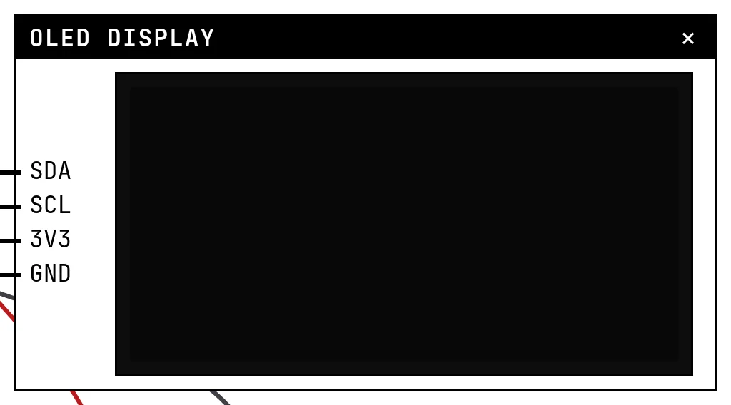
What it is
The 0.96″ OLED module is the most common small screen in hobby projects: 128 by 64 pixels, monochrome, driven by an SSD1306 controller over I²C. The controller keeps the image in its own memory; the firmware draws in RAM with a library and sends the whole frame with display().
In the simulator
The block is the glass, pixel for pixel: what the module's memory contains is what you see, including inversion, contrast and the hardware scroll. The I²C address setting (0x3C or 0x3D) must match the one the code uses in begin(), and the Pixel color setting only changes the glass — white, blue, or the two-tone panel with the first 16 rows in yellow.
Pins
| Pin | What it is |
|---|---|
| SDA | I²C data — to a GPIO (21 by default in the libraries) |
| SCL | I²C clock — to a GPIO (22 by default) |
| 3V3 | power — to a 3V3 symbol |
| GND | ground — to a GND symbol |
Wiring
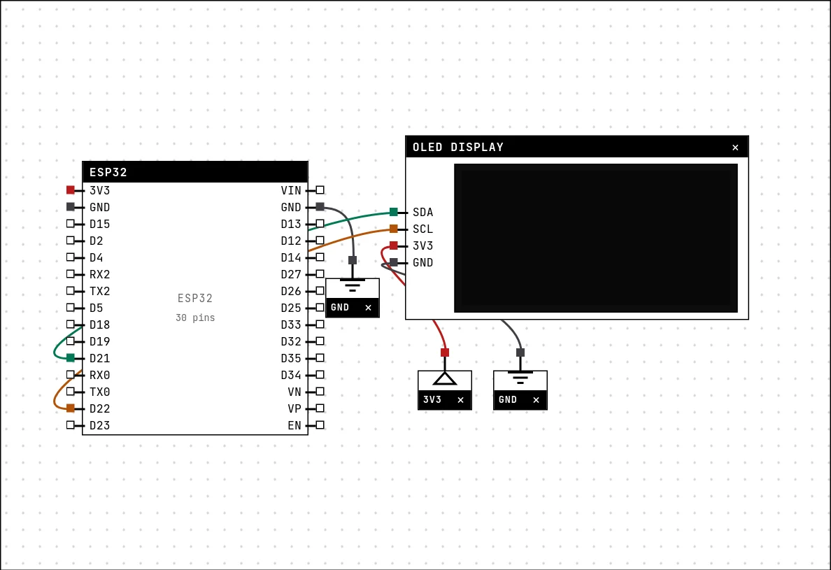
The circuit below is the example Dashboard on the OLED display from the lab — open it with Project → Open example… and it comes ready to run.
| OLED display pin | Goes to |
|---|---|
| SDA | D21 on the board (GPIO 21) |
| SCL | D22 on the board (GPIO 22) |
| 3V3 | a 3V3 symbol |
| GND | a GND symbol |
Settings
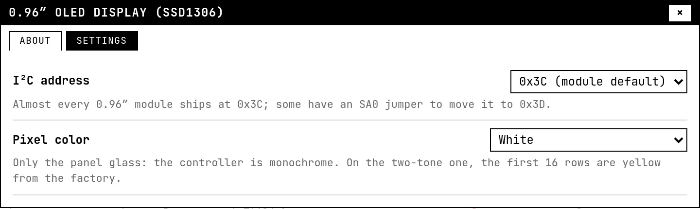
Double-click the block's title bar to open its card, then the Settings tab. Changes apply to the running simulation right away.
| Setting | Accepts | Default | Notes |
|---|---|---|---|
| I²C address | 0x3C (module default) · 0x3D (SA0 to VCC) | 0x3C (module default) | Almost every 0.96″ module ships at 0x3C; some have an SA0 jumper to move it to 0x3D. |
| Pixel color | White · Blue · Yellow + blue (two-tone) | White | Only the panel glass: the controller is monochrome. On the two-tone one, the first 16 rows are yellow from the factory. |
Code
#include <Arduino.h>
#include <Wire.h>
#include <Adafruit_GFX.h>
#include <Adafruit_SSD1306.h>

// The 0.96" one has exactly 128x64 pixels. Getting the height wrong here makes
// the drawing come out interlaced on the real module.
Adafruit_SSD1306 tela(128, 64, &Wire, -1);

int x = 20, y = 14, vx = 3, vy = 2;   // ball and speed
unsigned long voltas = 0;

void setup() {
  Serial.begin(115200);
  delay(300);
  Wire.begin(21, 22);                 // SDA and SCL: any GPIOs will do
  if (!tela.begin(SSD1306_SWITCHCAPVCC, 0x3C)) {
    Serial.println("SSD1306 not found — check SDA, SCL and the address");
    for (;;) delay(1000);
  }
  Serial.println("display ready");
}

void loop() {
  // ALL the drawing happens in the ESP32 RAM; the screen only changes on display()
  tela.clearDisplay();

  tela.setTextColor(SSD1306_WHITE);
  tela.setTextSize(1);
  tela.setCursor(0, 0);
  tela.println("STANNUM");

  tela.setTextSize(2);                // 2x font: 12x16 per character
  tela.setCursor(0, 12);
  tela.println(voltas);

  tela.drawRect(0, 32, 128, 32, SSD1306_WHITE);   // the ball's "court"
  tela.fillCircle(x, y + 32, 4, SSD1306_WHITE);

  // 8-bit physics: hit the edge, flip
  x += vx; y += vy;
  if (x <= 5 || x >= 122) vx = -vx;
  if (y <= 5 || y >= 26)  vy = -vy;

  tela.display();                     // sends the 1024 bytes over I2C
  voltas++;
  delay(40);
}Everything is Adafruit_SSD1306 plus Adafruit_GFX: clearDisplay(), text with setCursor/println, drawRect, fillCircle… and then display(), which sends the 1024 bytes over I²C. Nothing appears on the glass until that call — the most common surprise with this module. Wire.begin(21, 22) chooses the pins; any two GPIOs work.
Run it
Press Build and run. The first build of a project takes a while; after that, only what changed is rebuilt.
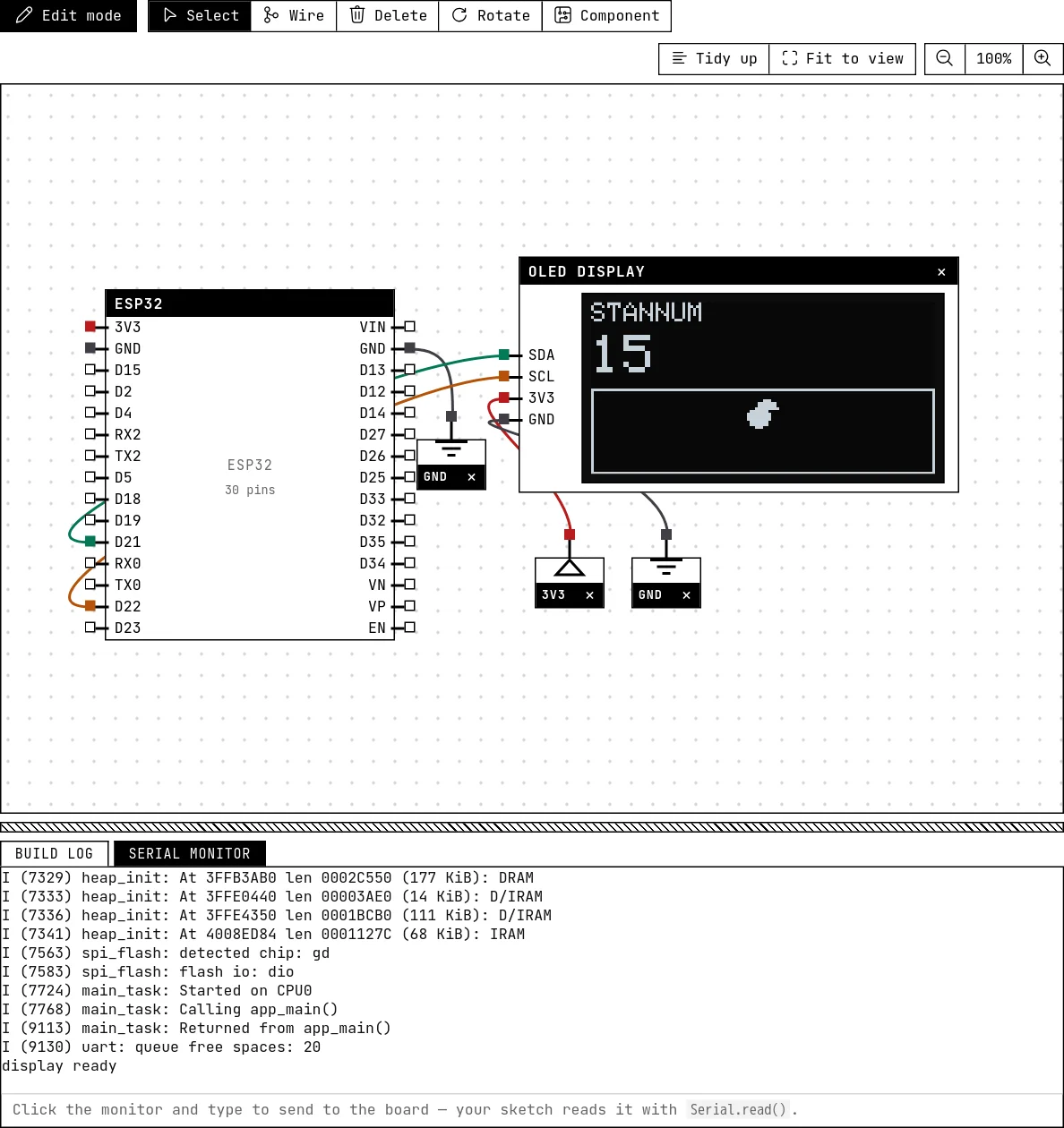
The screen shows the title, a counter in large type and a ball bouncing inside a rectangle, redrawn about 25 times a second. Change the address in Settings to 0x3D while it runs and the screen goes blank: the module stopped answering at the address the code talks to.
How the simulation models it
- The simulation emulates the SSD1306 controller itself: command bytes, addressing modes, the 1024-byte frame memory, display on/off, inversion, contrast, flips, start line and the hardware scroll commands. Libraries work unmodified because they talk to the same registers.
- The block redraws when the memory changes, up to about 20 frames per second.
- Any I²C address the code uses must match the block's setting; the bus is resolved by address, not by pin.
Try this
- Print the reading of a potentiometer in size-3 digits, updated only when it changes.
- Call
startscrollleft(0, 7)after the first frame and watch the whole screen scroll by itself — the controller does it, not your loop.
See also
- Character LCD with I²C backpack — The classic 16×2 text display cut down to two wires by a small I²C board — text, custom characters and a backlight.
- Color TFT display (ST7735 / ST7789) — The 7-pin SPI color screen in five sizes, from 80×160 to 240×320, with the quirks of the real controller — including the white screen of a wrong init.
- BME280 environmental sensor — Temperature, pressure and humidity from one I²C chip, read by the real Adafruit library — calibration and all.