Tutorials / Output
RGB LED
Three LEDs in one package, one GPIO each — red, green and blue mix into eight colors.
- Joystick
- RGB LED
What it is
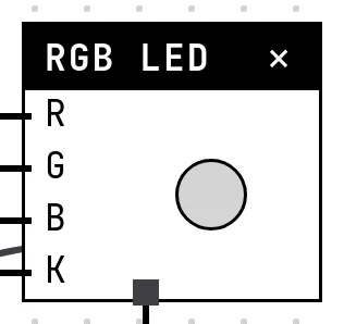
An RGB LED is three LEDs sharing one dome and, in the common-cathode kind modeled here, one ground leg. Drive each anode from its own GPIO and the eye adds the three lights: red and green make yellow, all three make white.
In the simulator
The block is a single dome whose color is the mix of the three channels. Each channel is either on or off, so the palette is the eight combinations of R, G and B. In the example, a joystick chooses: X to the right lights red, Y up lights blue, the stick's button lights green.
Pins
| Pin | What it is |
|---|---|
| R | red anode — to a GPIO |
| G | green anode — to a GPIO |
| B | blue anode — to a GPIO |
| K | common cathode — to a GND symbol |
Wiring
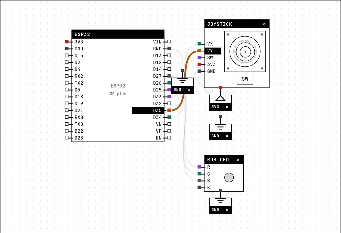
The circuit below is the example RGB LED colors with a joystick from the lab — open it with Project → Open example… and it comes ready to run.
| RGB LED pin | Goes to |
|---|---|
| R | D25 on the board (GPIO 25) |
| G | D26 on the board (GPIO 26) |
| B | D27 on the board (GPIO 27) |
| K | a GND symbol |
Code
#include <Arduino.h>

const int VX = 34;   // joystick X axis (ADC)
const int VY = 35;   // Y axis (ADC)
const int SW = 33;   // joystick button
const int R = 25, G = 26, B = 27;

void setup() {
  Serial.begin(115200);
  pinMode(R, OUTPUT); pinMode(G, OUTPUT); pinMode(B, OUTPUT);
  pinMode(SW, INPUT_PULLUP);
}

void loop() {
  int x = analogRead(VX);          // 0..4095, at rest ~2048
  int y = analogRead(VY);
  bool apertado = digitalRead(SW) == LOW;

  digitalWrite(R, x > 2800 ? HIGH : LOW);
  digitalWrite(B, y > 2800 ? HIGH : LOW);
  digitalWrite(G, apertado ? HIGH : LOW);

  Serial.printf("x=%d y=%d button=%d\n", x, y, apertado);
  delay(100);
}
digitalWrite on three pins is all it takes. The joystick's two axes are read with analogRead and compared with a threshold (2800 of 4095) to decide whether a channel goes on; the stick's button is read as a digital input with the pull-up on.
Run it
Press Build and run. The first build of a project takes a while; after that, only what changed is rebuilt.
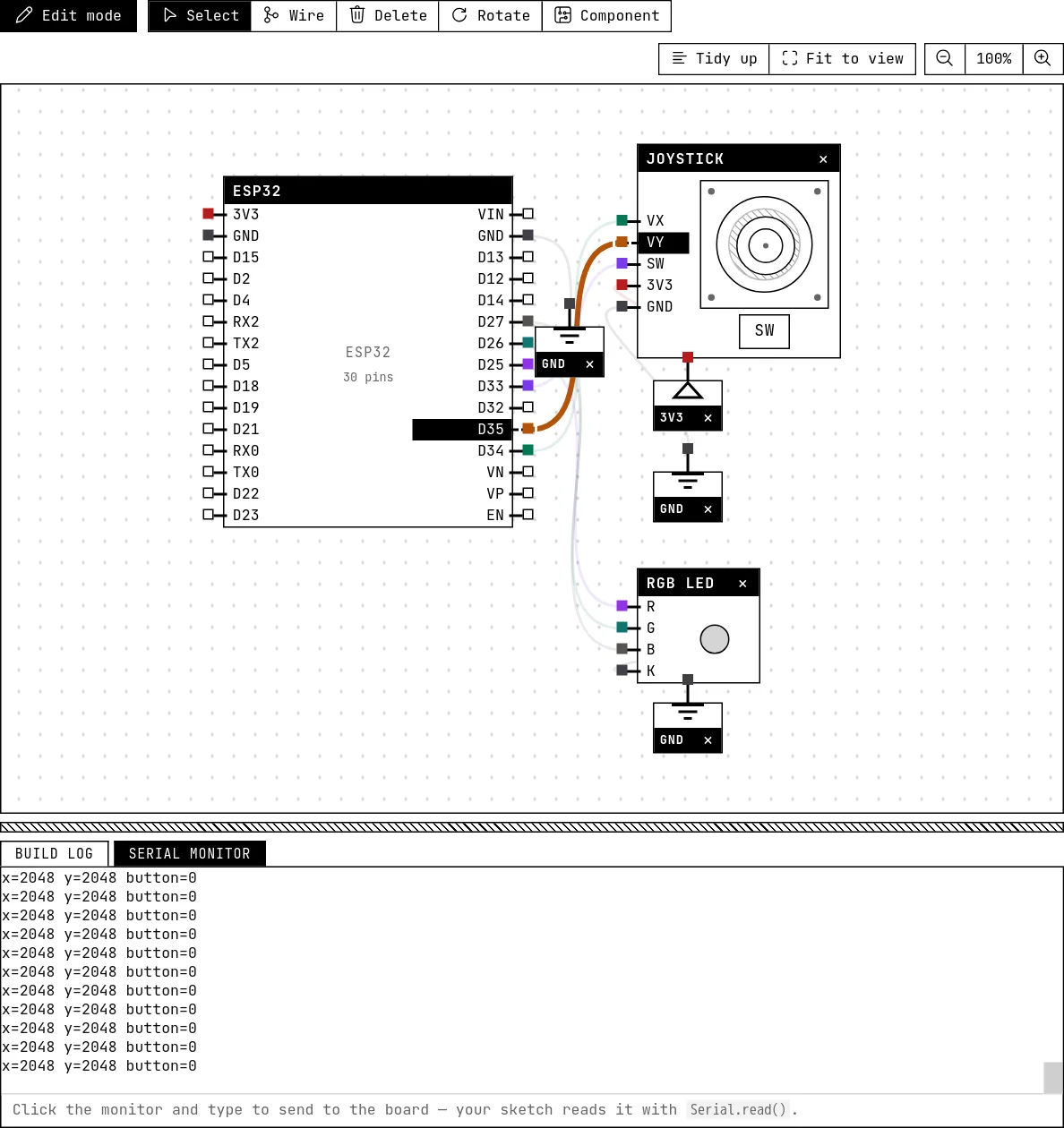
Drag the stick on the joystick block and watch the dome change color; release it and it springs back to the center (every channel off). Press the stick's SW button for green.
How the simulation models it
- Each channel follows the level of its GPIO: 0 or 255 in the color mix, nothing in between. PWM dimming (which is how real projects get 16 million colors) is not shown as intermediate brightness.
- Only the common-cathode package is modeled: HIGH on a channel lights it. A common-anode LED would light on LOW.
Try this
- Cycle through the eight colors with a
forloop over the three bits, one color per second. - Make the color depend on the potentiometer of another example: below 1/3 red, in the middle green, above 2/3 blue.
See also
- LED — The first output of every project: a GPIO set HIGH lights it, LOW turns it off.
- Analog joystick — Two potentiometers and a button in one stick: two ADC channels and one digital input.