Tutorials / Sensors
MQ-2 gas and smoke sensor
An analog reading that rises with gas, plus a digital alarm output with a threshold you set on the module.
- MQ-2 (gas)
- Active buzzer
- LED
What it is
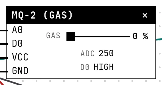
The MQ-2 has a heated element whose resistance drops when flammable gas or smoke reaches it. The module gives two outputs: A0, the raw analog value, and D0, the output of a comparator with a threshold set by the blue trimmer on the board — LOW when gas is detected on most modules. The reading is relative: an MQ sensor is not calibrated in ppm.
In the simulator
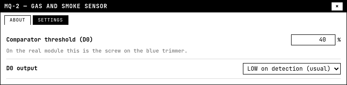
The block has a Gas slider (0 to 100 %) and shows the ADC count and the level of D0. In Settings, the Comparator threshold is the trimmer (40 % by default) and D0 output chooses the polarity. Notice the reading never reaches zero: clean air already gives a floor, like the real part.
Pins
| Pin | What it is |
|---|---|
| A0 | A0, the analog reading — to a GPIO with an ADC |
| D0 | D0, the comparator's alarm output — to a GPIO (optional) |
| VCC | power — to a 3V3 symbol |
| GND | ground — to a GND symbol |
Wiring
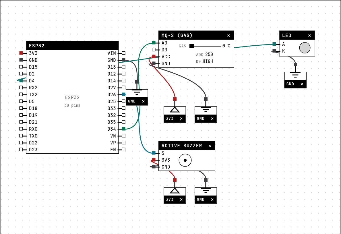
The circuit below is the example Gas alarm — MQ-2 from the lab — open it with Project → Open example… and it comes ready to run.
| MQ-2 (gas) pin | Goes to |
|---|---|
| A0 | D34 on the board (GPIO 34) |
| D0 | left unconnected |
| VCC | a 3V3 symbol |
| GND | a GND symbol |
Settings
Double-click the block's title bar to open its card, then the Settings tab. Changes apply to the running simulation right away.
| Setting | Accepts | Default | Notes |
|---|---|---|---|
| Comparator threshold (D0) | 0 to 100 % | 40 % | On the real module this is the screw on the blue trimmer. |
| D0 output | LOW on detection (usual) · HIGH on detection | LOW on detection (usual) |
Code
#include <Arduino.h>

// The MQ-2 does not come calibrated in ppm: the reading is RELATIVE. In real
// life you record the clean-air value and alarm on the change — here a fixed
// threshold is enough for the exercise.
const int GAS = 34, BUZZER = 26, LED = 4;
const int LIMIAR = 1800;

void setup() {
  Serial.begin(115200);
  pinMode(BUZZER, OUTPUT);
  pinMode(LED, OUTPUT);
}

void loop() {
  int leitura = analogRead(GAS);
  bool alarme = leitura > LIMIAR;
  digitalWrite(BUZZER, alarme);
  digitalWrite(LED, alarme);
  Serial.printf("gas=%4d %s\n", leitura, alarme ? "*** ALARM ***" : "ok");
  delay(300);
}
Only A0 is used: analogRead, compared with 1800, drives the buzzer and the LED. The comment in the sketch says the honest thing about MQ sensors: record the clean-air value and alarm on the change.
Run it
Press Build and run. The first build of a project takes a while; after that, only what changed is rebuilt.
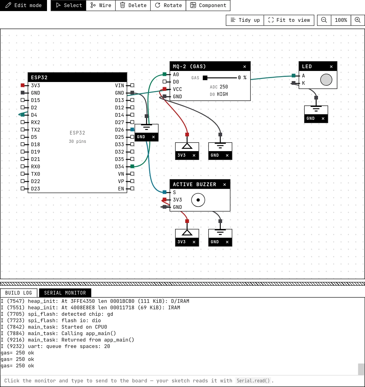
Drag the slider up: past the threshold the buzzer and the LED go on and the serial monitor prints “*** ALARM ***”.
How the simulation models it
- ADC count = 250 + slider × (4095 − 250): a floor of 250 in clean air, 4095 at 100 %.
- D0 trips when the slider reaches the threshold in Settings, with the polarity chosen there — the comparator is modeled, the heater's warm-up time (minutes on the bench) is not.
Try this
- Wire D0 to a GPIO and alarm on it instead of on A0 — then move the threshold in Settings and see the code follow without a rebuild.
- Print the reading relative to the value seen at start-up (“+12 %”), the way a real installation would.
See also
- Soil moisture and rain sensors — Two resistive boards with the same electronics: a dry board reads HIGH, and a comparator gives a digital alarm.
- Active buzzer — A beeper with its own fixed tone: HIGH sounds it, LOW silences it — and it really sounds in your browser.