Tutorials / Output
Relay, lamp and the mains
The electromechanical switch that lets a 3.3 V pin drive a lamp on the mains — with the AC side kept away from the board.
- Button
- Relay
- AC supply
- Lamp
What it is
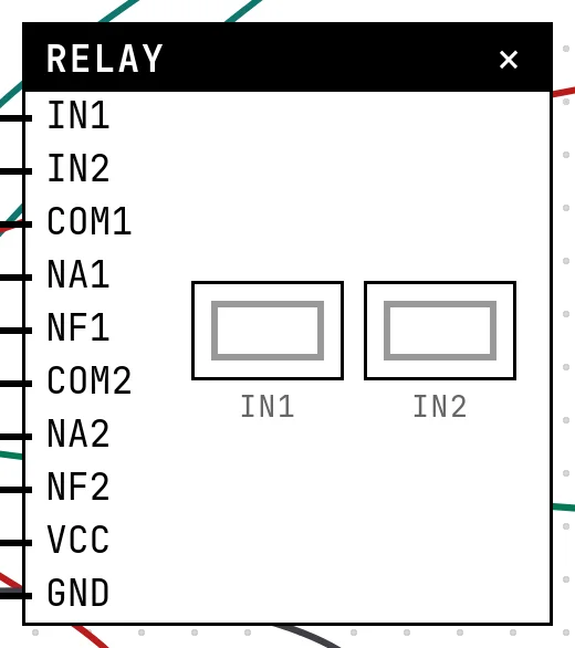
A relay is a switch operated by an electromagnet. The coil side is low voltage and is driven by a GPIO; the contact side carries whatever the load needs — a lamp on the mains, a pump, a motor — and never touches the board. Each channel has three terminals: COM (common), NA (normally open: closed to COM while the coil is energized) and NF (normally closed: closed to COM while it is not).
In the simulator
The block has one IN pin per channel and, on the load side, the COM/NA/NF terminals of each. A channel's square lights when its coil is energized. To make it do something, the catalog has two more parts: the Lamp, and the AC supply — the wall outlet, with LINE and NEUTRAL. The lamp lights when its two terminals reach line and neutral through closed contacts.
Pins
| Pin | What it is |
|---|---|
| IN1 | signal — wire it to a GPIO of the board |
| IN2 | signal — wire it to a GPIO of the board |
| COM1 | |
| NA1 | |
| NF1 | |
| COM2 | |
| NA2 | |
| NF2 | |
| VCC | power for the coil driver — to a 3V3 symbol |
| GND | ground — to a GND symbol |
Lamp
| Pin | What it is |
|---|---|
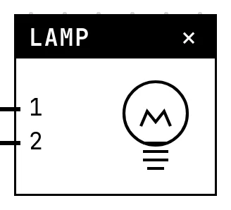
| 1 | one terminal of the filament — to a relay contact or to NEUTRAL; the lamp has no polarity |
| 2 | the other terminal — to NEUTRAL or to a relay contact |
AC supply
| Pin | What it is |
|---|---|
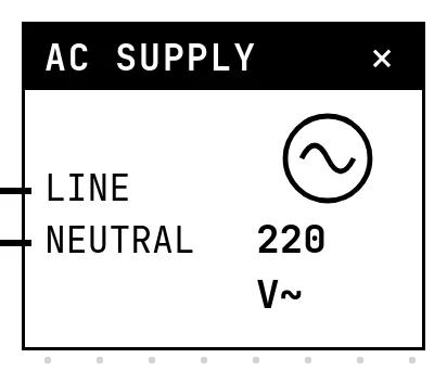
| LINE | LINE, the live wire of the outlet — to the relay's COM, never to the board |
| NEUTRAL | NEUTRAL — to the lamp's other terminal, never to the board |
Wiring
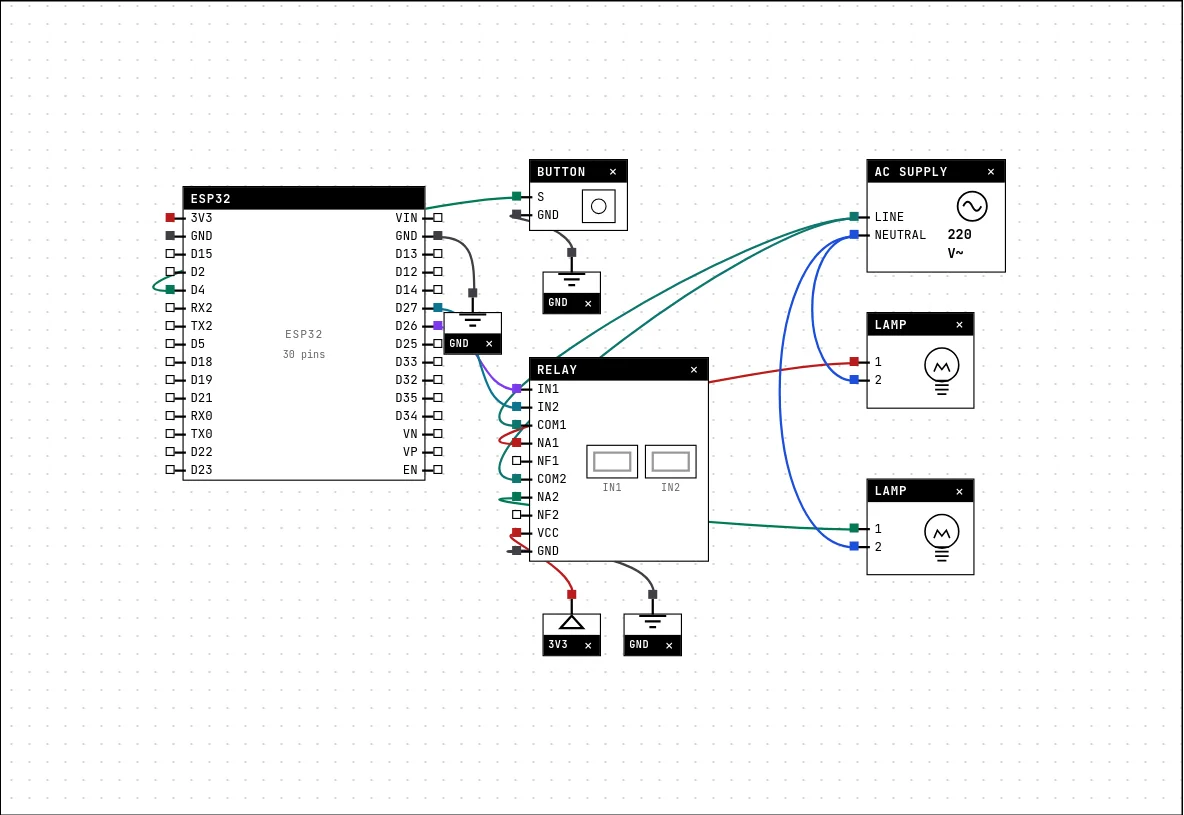
The circuit below is the example Lighting with a relay and lamps from the lab — open it with Project → Open example… and it comes ready to run.
| Relay pin | Goes to |
|---|---|
| IN1 | D26 on the board (GPIO 26) |
| IN2 | D27 on the board (GPIO 27) |
| COM1 | LINE of the AC supply |
| NA1 | 1 of the Lamp |
| NF1 | left unconnected |
| COM2 | LINE of the AC supply |
| NA2 | 1 of the Lamp |
| NF2 | left unconnected |
| VCC | a 3V3 symbol |
| GND | a GND symbol |
| Lamp pin | Goes to |
|---|---|
| 1 | NA1 of the Relay |
| 2 | NEUTRAL of the AC supply |
| AC supply pin | Goes to |
|---|---|
| LINE | COM1 of the Relay COM2 of the Relay |
| NEUTRAL | 2 of the Lamp 2 of the Lamp |
This is the electrician's circuit: line from the AC supply to COM; the lamp between NA and neutral. Energize the coil and COM–NA closes: the lamp is across the mains. Note that nothing from the right side of the drawing goes anywhere near the board — the AC supply's setting (220, 127 or 110 V) changes labels and warnings, never a voltage on a GPIO.
Settings
Double-click the block's title bar to open its card, then the Settings tab. Changes apply to the running simulation right away.
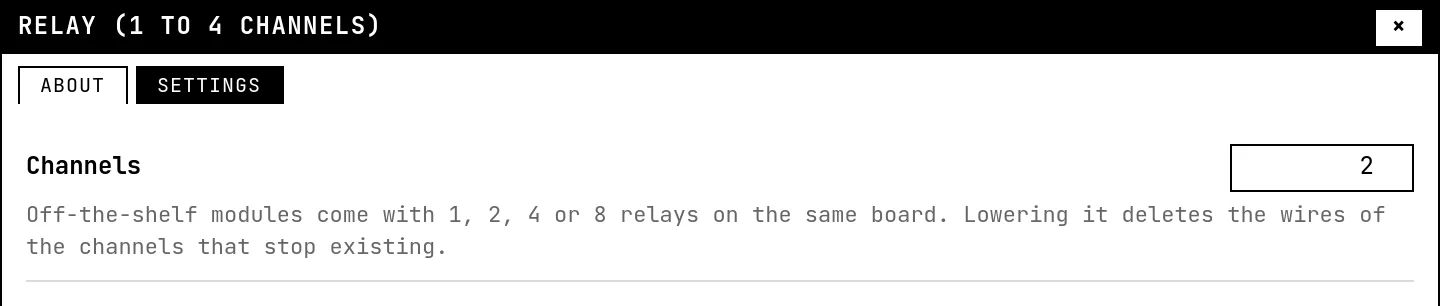
| Setting | Accepts | Default | Notes |
|---|---|---|---|
| Channels | 1 to 4 | 1 | Off-the-shelf modules come with 1, 2, 4 or 8 relays on the same board. Lowering it deletes the wires of the channels that stop existing. |
AC supply

| Setting | Accepts | Default | Notes |
|---|---|---|---|
| Mains voltage | 220 V · 127 V · 110 V | 220 V | It only changes the label and the warnings: the lamp lights the same. It NEVER goes near the GPIOs. |
Code
#include <Arduino.h>

// Channel 1: switch (the button toggles). Channel 2: automatic blinker.
// HIGH on IN energizes the coil and closes COM-NA — the lamp lights on 220 V
// WITHOUT the 220 V going anywhere near the ESP32: that is the point of a relay.
const int BOTAO = 4, LUZ = 26, PISCA = 27;
bool acesa = false;

void setup() {
  Serial.begin(115200);
  pinMode(BOTAO, INPUT_PULLUP);
  pinMode(LUZ, OUTPUT);
  pinMode(PISCA, OUTPUT);
  Serial.println("press the button to turn the light on");
}

void loop() {
  static bool antes = HIGH;
  bool agora = digitalRead(BOTAO);
  if (antes == HIGH && agora == LOW) {      // edge: pressed
    acesa = !acesa;
    digitalWrite(LUZ, acesa);
    Serial.printf("light %s\n", acesa ? "ON" : "off");
    delay(30);                              // simple debounce
  }
  antes = agora;

  digitalWrite(PISCA, (millis() / 1000) % 2);   // channel 2 blinks at 0.5 Hz
}
Channel 1 is a toggle: the button's falling edge flips a boolean and writes it to the coil pin. Channel 2 blinks by itself with millis(). digitalWrite(pin, HIGH) energizes a channel.
Run it
Press Build and run. The first build of a project takes a while; after that, only what changed is rebuilt.
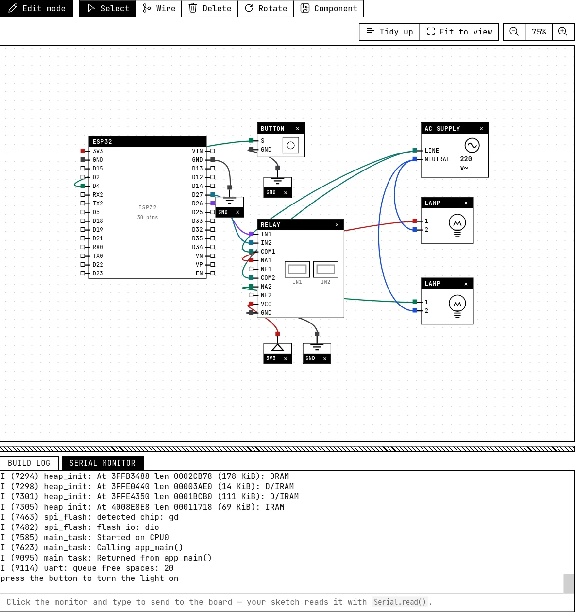
Press the button on the canvas: channel 1 lights, its COM–NA contact closes and the first lamp lights. The second lamp blinks every second on its own. The serial monitor logs each toggle.
How the simulation models it
- A channel is energized while its IN pin is HIGH. Many off-the-shelf relay boards are active-low (LOW energizes); check yours before moving a sketch to the bench.
- The load side is solved as switches: COM joins NA when energized, NF otherwise. A lamp lights when one terminal reaches LINE and the other NEUTRAL through those contacts, in any combination of wires.
- Wire LINE or NEUTRAL to any pin of the board and the lab raises its most serious warning — see Power, ground and the voltmeter.
- The Channels setting (1 to 4) grows the block; lowering it deletes the wires of the channels that stop existing.
Try this
- Move the lamp from NA to NF and predict what happens before running: the lamp should be on at rest and go off when you press.
- Wire LINE straight to a GPIO and read the warning. Then undo it.
- Use a PIR sensor instead of the button to light the lamp for 5 seconds after motion.
See also
- Power, ground and the voltmeter — The GND and 3V3 symbols, the adjustable power supply, the voltmeter, and the electrical warnings the lab raises when a wire would damage the board.
- Push button — A momentary contact: HIGH while released, LOW while pressed — the first digital input.
- PIR motion sensor — The HC-SR501: it raises its output for a few seconds when something warm moves in front of it.