Tutorials / Power & measuring
Power, ground and the voltmeter
The GND and 3V3 symbols, the adjustable power supply, the voltmeter, and the electrical warnings the lab raises when a wire would damage the board.
GND and 3V3 are symbols, not parts
In the catalog's Power category there are two symbols: GND and 3V3. Dropping one on the canvas does not add a component — it adds a label for a global net, exactly like the ground symbol of a schematic. Every GND symbol, every GND pin of the board and everything wired to any of them is one node; the same goes for 3V3 and the board's 3V3 pin. That is why a module gets its own pair of symbols right next to it instead of three long wires back to the board — the drawing stays readable and the circuit is the same.
The lab colors these two nets the same way on every project: GND in dark gray, 3V3 in red.
The adjustable power supply
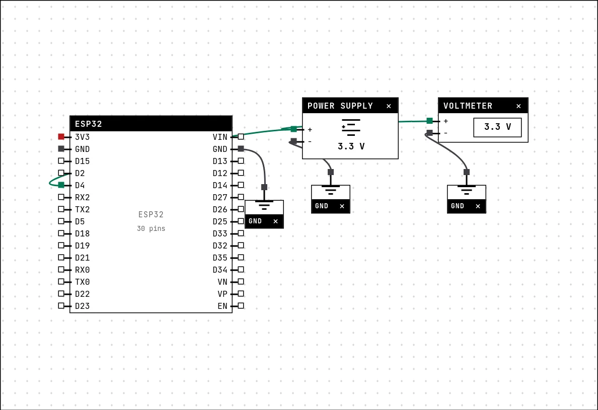
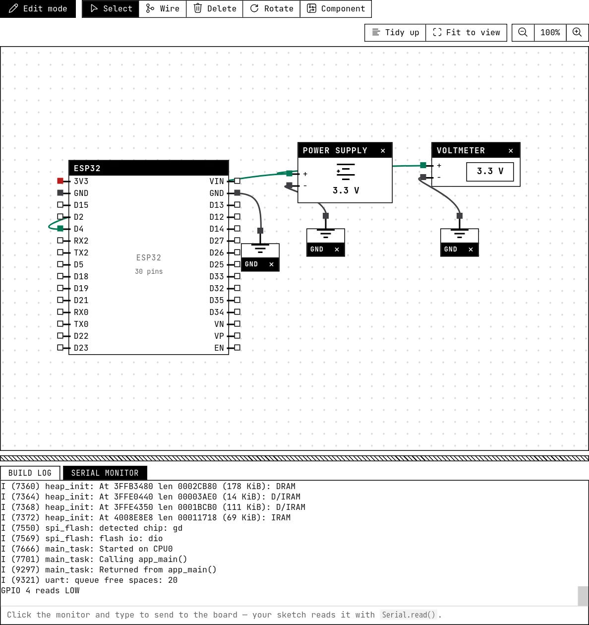
The Power supply block is a voltage source you set, from −30 V to 60 V. Its − pin is the 0 V reference — think of it as sitting on the common ground — and + carries the voltage from the card's Settings tab. It exists to ask “what if?”: what does a GPIO see at 3.3 V, and what happens at 5 V.

#include <Arduino.h>

// GPIO 4 is wired to the + of an adjustable supply. At 3.3 V it reads HIGH.
// Turn the supply up to 5 V in its settings and watch the lab shout — on a
// real board that is the moment the pin dies.
const int PIN = 4;

void setup() {
  Serial.begin(115200);
  pinMode(PIN, INPUT);
}

void loop() {
  Serial.println(digitalRead(PIN) ? "GPIO 4 reads HIGH" : "GPIO 4 reads LOW");
  delay(1000);
}
The voltmeter
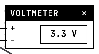
The Voltmeter shows the difference of potential between its + and − pins. With both probes loose it shows “—”, like a meter with its leads in the air; hovering it tells what each probe sees. Its Range setting mimics a bench multimeter: automatic, volts, or millivolts — on the mV range, 3.3 V shows as 3300 mV, handy for reading small differences.

The electrical warnings
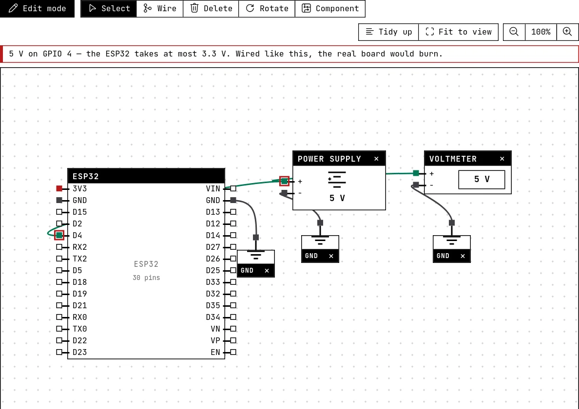
Before and during a simulation, the lab looks at every net that touches a pin of the board and warns when a real board would suffer. The warning appears above the canvas and the guilty pins are marked. The checks:
| Situation | What the lab says |
|---|---|
| More than 3.3 V on a GPIO (a 5 V supply, VIN or 5V wired to a GPIO) | Error — the pin would burn. |
| A negative voltage on a GPIO | Error — the pins do not tolerate it. |
| Between 0 V and about 2.5 V on a GPIO | Warning — the undefined zone: the chip only guarantees a HIGH reading from 0.75 × 3.3 V up. It may read either. |
| Two different voltages tied to the same net (3V3 and GND, two supplies…) | Error — a short circuit. |
| The board's 3V3 fed with less than 3.0 V | Warning — brownout: the chip resets by itself, worse with Wi-Fi on. |
| Anything wired to GPIOs 6–11 on a 38-pin board | Error — those are the flash pins; the chip will not boot. |
| The mains (the AC supply block) touching any board pin | Error — the worst one: it destroys the board and, on a bench, is a shock hazard. Mains only meets the relay's contacts. |
What is — and is not — modeled
- The voltage model is about potentials imposed by sources: the GND and 3V3 nets, the power supply, the board's power pins, and the GPIOs the firmware drives (a GPIO set HIGH is a 3.3 V source on its net). A net with no source is “floating”, and the voltmeter shows nothing for it.
- There is no current and no resistance: the lab does not solve circuits. A resistor divider or an LED's forward drop are not computed, so the voltmeter across a potentiometer's wiper does not show the divided voltage — the potentiometer block calculates it itself and shows it on its face. The warnings are about levels, which is what damages boards.
- The AC side (mains supply, lamp, relay contacts) is a separate world: the lamp lights when its two terminals reach line and neutral through closed relay contacts, and the mains never turns into “volts” on a GPIO. See Relay, lamp and the mains.
See also
- ESP32 boards — Eight boards to choose from, pin by pin: which GPIOs reach the header, which are input-only, which have an ADC, and which must be left alone.
- Potentiometer — A variable resistor whose wiper divides 3.3 V — the first analog input, read with analogRead().
- Relay, lamp and the mains — The electromechanical switch that lets a 3.3 V pin drive a lamp on the mains — with the AC side kept away from the board.