Tutorials / Sensors
Magnetometer (HMC5883L compass)
Three magnetic axes on I²C; atan2 of X and Y is the heading — the electronic compass, without a library.
- Magnetometer
- RGB LED
What it is
The HMC5883L measures the magnetic field along three axes. Earth's field is weak — around 23 µT horizontally in Brazil, 50 µT in Europe — and the heading is the angle of the horizontal component: atan2(y, x). The chip has a fixed address, 0x1E, and one famous trap: its data registers come in the order X, Z, Y.
In the simulator
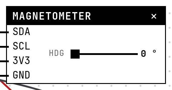
The block has a Hdg slider, the compass heading in degrees. Settings hold the field strength in µT (it changes the raw counts, like moving to another latitude — or bringing a magnet close, which saturates the sensor).
Pins
| Pin | What it is |
|---|---|
| SDA | I²C data — to a GPIO |
| SCL | I²C clock — to a GPIO |
| 3V3 | power — to a 3V3 symbol |
| GND | ground — to a GND symbol |
Wiring
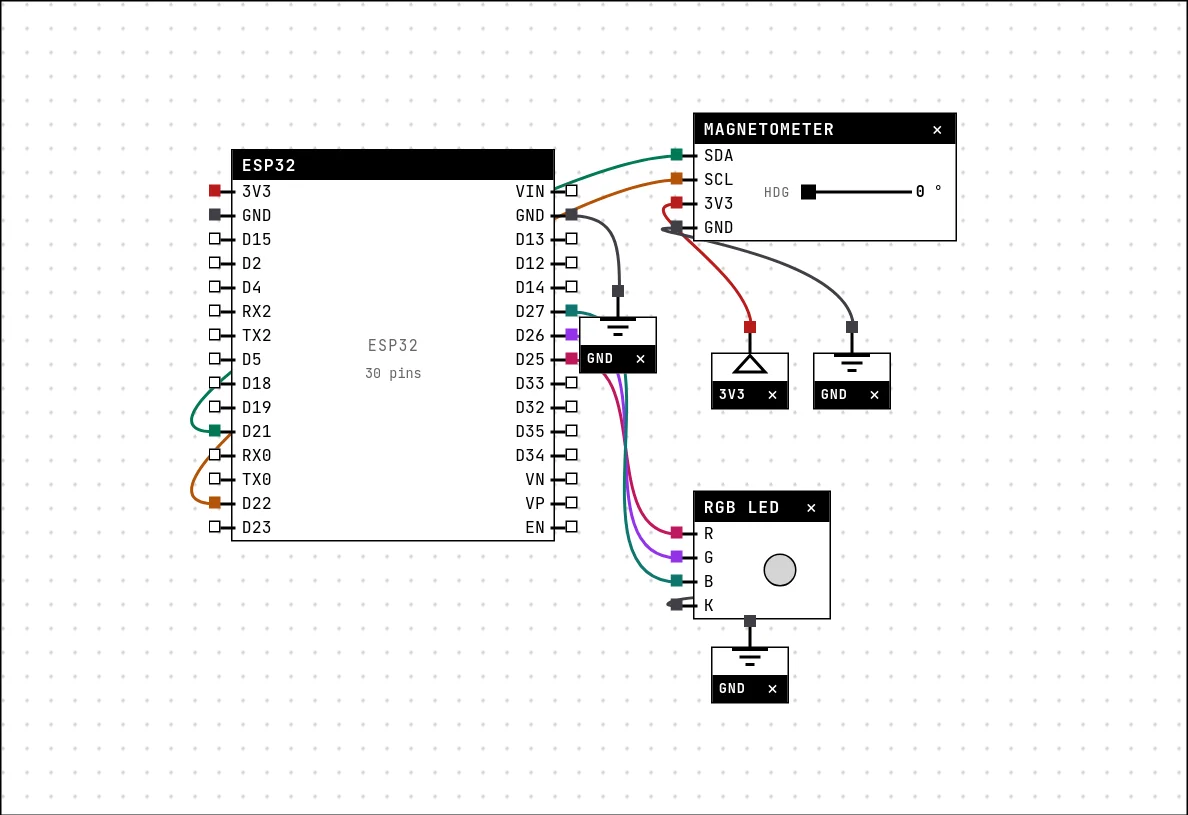
The circuit below is the example Compass with a magnetometer from the lab — open it with Project → Open example… and it comes ready to run.
| Magnetometer pin | Goes to |
|---|---|
| SDA | D21 on the board (GPIO 21) |
| SCL | D22 on the board (GPIO 22) |
| 3V3 | a 3V3 symbol |
| GND | a GND symbol |
Settings
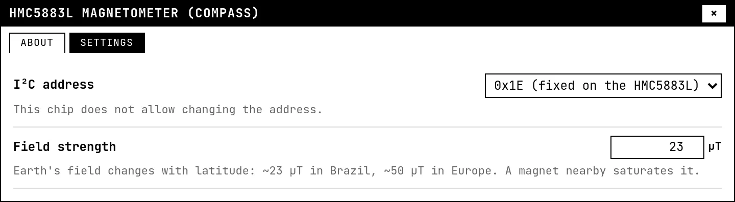
Double-click the block's title bar to open its card, then the Settings tab. Changes apply to the running simulation right away.
| Setting | Accepts | Default | Notes |
|---|---|---|---|
| I²C address | 0x1E (fixed on the HMC5883L) | 0x1E (fixed on the HMC5883L) | This chip does not allow changing the address. |
| Field strength | 5 to 65 µT | 23 µT | Earth's field changes with latitude: ~23 µT in Brazil, ~50 µT in Europe. A magnet nearby saturates it. |
Code
#include <Arduino.h>
#include <Wire.h>

const uint8_t ADDR = 0x1E;         // HMC5883L
const int R = 25, G = 26, B = 27;

int16_t lerEixo(uint8_t reg) {
  Wire.beginTransmission(ADDR); Wire.write(reg); Wire.endTransmission();
  Wire.requestFrom(ADDR, (uint8_t)2);
  int hi = Wire.read(), lo = Wire.read();
  return (int16_t)((hi << 8) | lo);
}

void setup() {
  Serial.begin(115200);
  delay(300);
  Wire.begin(21, 22);
  pinMode(R, OUTPUT); pinMode(G, OUTPUT); pinMode(B, OUTPUT);
}

void loop() {
  // WATCH the register order: X, Z, Y — not X, Y, Z
  int16_t x = lerEixo(0x03);
  int16_t z = lerEixo(0x05);
  int16_t y = lerEixo(0x07);

  float rumo = atan2((float)y, (float)x) * 180.0 / PI;
  if (rumo < 0) rumo += 360;

  const char *ponto = "?";
  if (rumo < 45 || rumo >= 315)      ponto = "N";
  else if (rumo < 135)               ponto = "E";
  else if (rumo < 225)               ponto = "S";
  else                               ponto = "W";

  digitalWrite(G, ponto[0] == 'N' ? HIGH : LOW);
  digitalWrite(R, ponto[0] == 'S' ? HIGH : LOW);
  digitalWrite(B, (ponto[0] == 'E' || ponto[0] == 'W') ? HIGH : LOW);

  Serial.printf("x=%d y=%d z=%d  heading=%.0f degrees  %s\n", x, y, z, rumo, ponto);
  delay(500);
}
No library: the sketch talks to the chip with Wire directly — a register address, then two bytes per axis, read in the chip's X, Z, Y order. atan2 gives the heading, and the RGB LED shows the quadrant: north green, south red, east and west blue.
Run it
Press Build and run. The first build of a project takes a while; after that, only what changed is rebuilt.
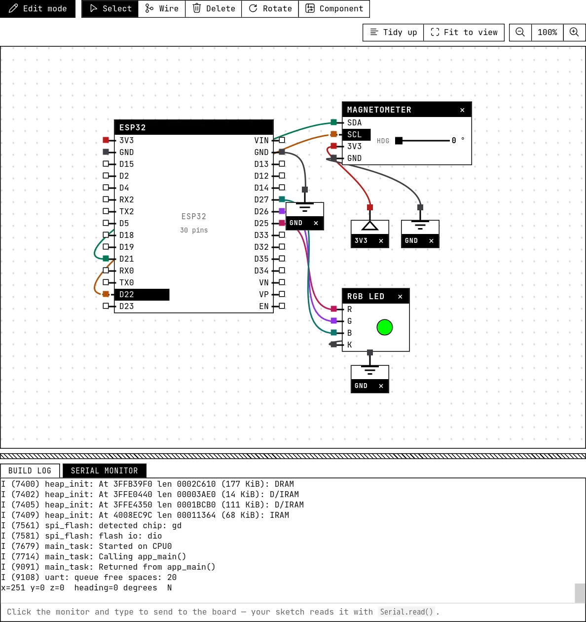
Drag the heading around the circle: the serial monitor prints the raw axes, the heading and the cardinal point, and the LED changes color at 45°, 135°, 225° and 315°.
How the simulation models it
- X and Y are the cosine and sine of the heading times the field strength, converted at the chip's factory gain (1090 counts per gauss); Z is zero. The status register always reports data ready; the identification registers read “H43”.
- No tilt compensation is needed because the sensor is always level here; on a bench, tilting the board changes the heading — which is why real compasses also read an accelerometer.
Try this
- Print the heading only when it changes by more than 5°.
- Set the field to 60 µT in Settings and check that the heading does not change — only the magnitude of the axes does.
See also
- MPU6050 accelerometer and gyroscope — Six axes on I²C: at rest the accelerometer measures gravity, and tilting redistributes it — that is how a phone knows it was turned.
- RGB LED — Three LEDs in one package, one GPIO each — red, green and blue mix into eight colors.