Tutorials / Output
8×8 LED matrix (MAX7219)
Sixty-four LEDs driven through three wires by a MAX7219 — pixel art in eight bytes.
- 8×8 matrix
What it is
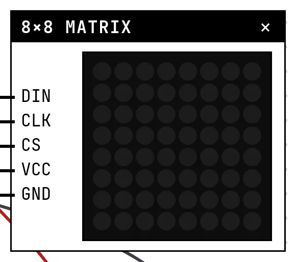
An 8×8 matrix on its own needs 16 pins scanned very fast. The MAX7219 does that scanning by itself: you send it eight bytes — one per row, one bit per LED — over a three-wire serial link, and it keeps the picture lit. Modules chain: the data out of one feeds the next.
In the simulator
The block shows the 64 LEDs in the color chosen in Settings, with brightness following the chip's intensity register. The example draws two frames of a heart and alternates them.
Pins
| Pin | What it is |
|---|---|
| DIN | data in — to a GPIO |
| CLK | clock — to a GPIO |
| CS | chip select (LOAD) — to a GPIO |
| VCC | power — to a 3V3 symbol |
| GND | ground — to a GND symbol |
Wiring
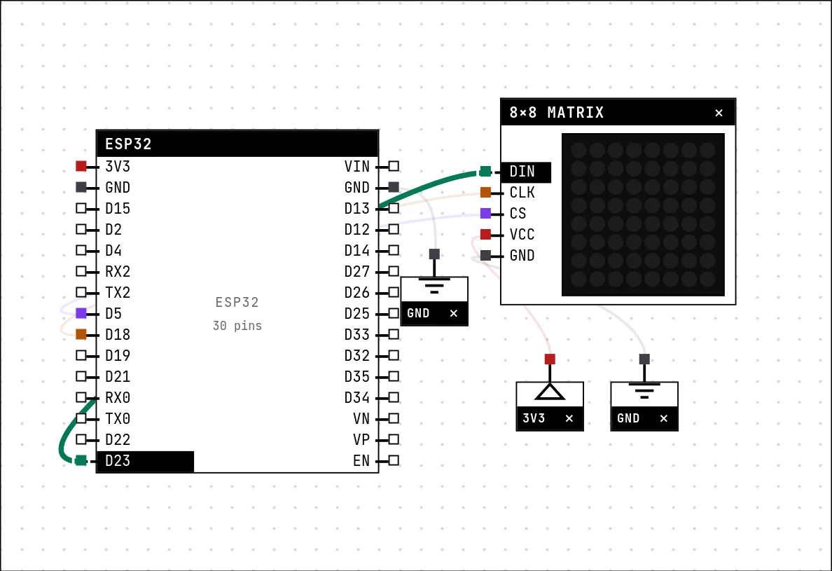
The circuit below is the example Beating heart on the 8×8 matrix from the lab — open it with Project → Open example… and it comes ready to run.
| 8×8 matrix pin | Goes to |
|---|---|
| DIN | D23 on the board (GPIO 23) |
| CLK | D18 on the board (GPIO 18) |
| CS | D5 on the board (GPIO 5) |
| VCC | a 3V3 symbol |
| GND | a GND symbol |
Settings
Double-click the block's title bar to open its card, then the Settings tab. Changes apply to the running simulation right away.

| Setting | Accepts | Default | Notes |
|---|---|---|---|
| LED color | Red · Green · Blue · Yellow · Orange · White | Red | The off-the-shelf module is red; green and blue exist made to order. |
Code
#include <Arduino.h>
#include <LedControl.h>

// Each row of the drawing is a byte: bit 7 is the leftmost column.
// Draw your own on graph paper and translate it into binary.
const byte CHEIO[8] = {
  B01100110, B11111111, B11111111, B11111111,
  B01111110, B00111100, B00011000, B00000000};
const byte VAZIO[8] = {
  B00000000, B01100110, B01111110, B01111110,
  B00111100, B00011000, B00000000, B00000000};

LedControl matriz(23, 18, 5, 1);   // DIN, CLK, CS, 1 module

void desenhar(const byte quadro[8]) {
  for (int linha = 0; linha < 8; linha++)
    matriz.setRow(0, linha, quadro[linha]);
}

void setup() {
  matriz.shutdown(0, false);       // the MAX7219 BOOTS UP asleep!
  matriz.setIntensity(0, 8);
  matriz.clearDisplay(0);
}

void loop() {
  desenhar(CHEIO);                 // systole
  delay(450);
  desenhar(VAZIO);                 // diastole
  delay(300);
}The LedControl library takes the three pins and the number of modules. Two things every MAX7219 sketch needs: shutdown(0, false), because the chip boots asleep, and setIntensity(). Then setRow(0, row, byte) paints one row — bit 7 is the leftmost LED. Draw on graph paper, translate each row into binary.
Run it
Press Build and run. The first build of a project takes a while; after that, only what changed is rebuilt.
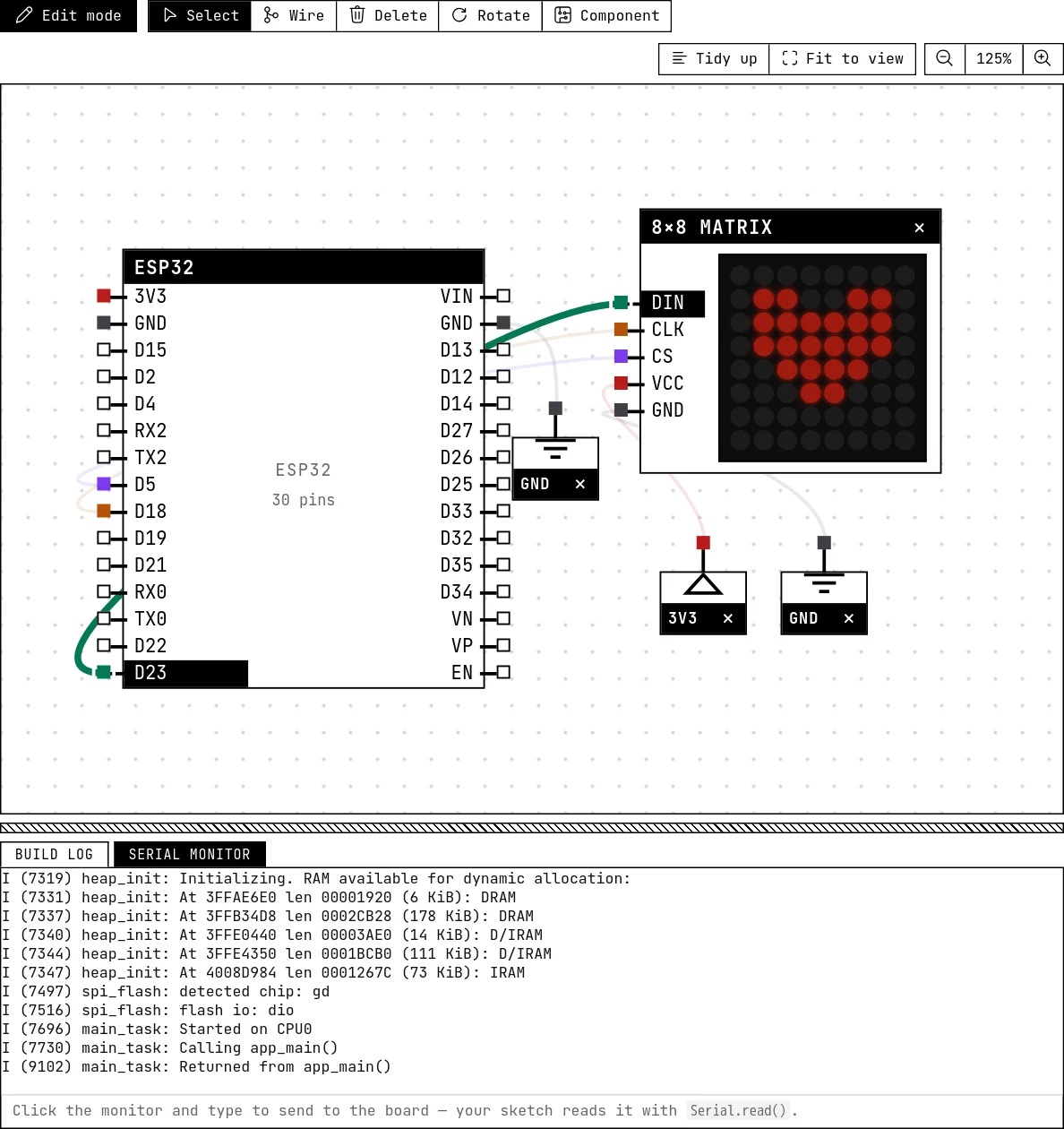
The heart beats: full for 450 ms, small for 300 ms. Comment out the shutdown() line and rebuild — nothing lights, exactly like the module out of the box.
How the simulation models it
- The simulation decodes the signal at the pin level — clock edges sample DIN, and the rising edge of CS latches a 16-bit (address, data) word — so any library, or plain
shiftOut, works. - Registers modeled: the eight digit rows, intensity, scan limit (rows past the limit stay off), shutdown and display test.
- One module. Daisy-chained matrices are not modeled: the bytes for a second module are ignored.
Try this
- Scroll a letter across the matrix by shifting each row byte one bit per frame.
- Add a button that switches between three animations.
See also
- LED bar — A row of 2 to 16 LEDs, one GPIO each — the level meter of every stereo.
- OLED display (SSD1306) — The 0.96″ 128×64 screen on I²C: two wires, an address, and a library that draws text and shapes.