Tutorials / Input
PIR motion sensor
The HC-SR501: it raises its output for a few seconds when something warm moves in front of it.
- PIR sensor
- Relay
- LED
What it is
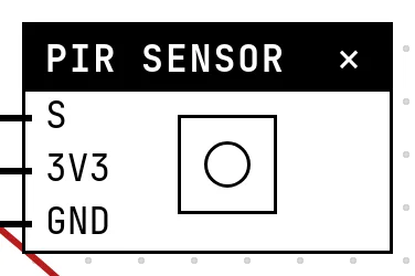
A passive infrared sensor watches for a change in the heat pattern in front of it — a person walking by — and holds its output HIGH for a while, set by a small trimmer on the module (a few seconds by default). No motion, LOW. It is the sensor of automatic lights and cheap alarms.
In the simulator
The block has a Motion button: click it and the output goes HIGH for the number of seconds chosen in Settings (Time in HIGH, 1 to 60 s, 3 by default), with a countdown shown on the block. Clicking again restarts the countdown, like a person still moving.
Pins
| Pin | What it is |
|---|---|
| S | signal — HIGH while motion is detected — to a GPIO |
| 3V3 | power — to a 3V3 symbol |
| GND | ground — to a GND symbol |
Wiring
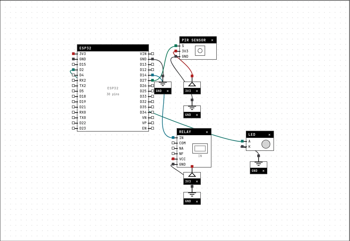
The circuit below is the example Motion alarm — PIR + relay from the lab — open it with Project → Open example… and it comes ready to run.
| PIR sensor pin | Goes to |
|---|---|
| S | D27 on the board (GPIO 27) |
| 3V3 | a 3V3 symbol |
| GND | a GND symbol |
Settings
Double-click the block's title bar to open its card, then the Settings tab. Changes apply to the running simulation right away.

| Setting | Accepts | Default | Notes |
|---|---|---|---|
| Time in HIGH | 1 to 60 s | 3 s | On the real sensor this time is a trimpot on the board. |
Code
#include <Arduino.h>

const int PIR = 27;
const int RELE = 14;
const int LED = 2;

void setup() {
  Serial.begin(115200);
  pinMode(PIR, INPUT);
  pinMode(RELE, OUTPUT);
  pinMode(LED, OUTPUT);
}

void loop() {
  if (digitalRead(PIR) == HIGH) {
    digitalWrite(RELE, HIGH);          // switch the load through the relay
    digitalWrite(LED, !digitalRead(LED));  // fast blink = alarm active
    Serial.println("motion detected!");
  } else {
    digitalWrite(RELE, LOW);
    digitalWrite(LED, LOW);
  }
  delay(150);
}
pinMode(PIR, INPUT) and digitalRead(PIR) == HIGH. While it is HIGH the sketch energizes the relay and toggles the LED on every pass; otherwise both go off. The 150 ms delay sets the blink rate of the warning.
Run it
Press Build and run. The first build of a project takes a while; after that, only what changed is rebuilt.
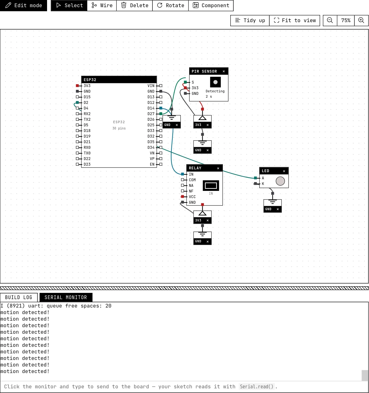
Click Motion: the relay's channel lights, the LED blinks fast and the serial monitor prints “motion detected!” until the countdown ends.
How the simulation models it
- The block drives the level: HIGH from the click until the countdown ends, then LOW. Real modules also have a retrigger mode and a warm-up minute after power-on; neither is modeled.
- The countdown survives redraws and the block being moved; deleting the block stops it.
Try this
- Turn it into an automatic light: lamp on the relay (see the relay guide), off 10 seconds after the last detection.
- Count detections per minute and print the rate.
See also
- Relay, lamp and the mains — The electromechanical switch that lets a 3.3 V pin drive a lamp on the mains — with the AC side kept away from the board.
- Reed switch — A contact that closes near a magnet — the sensor on every door and window alarm.
- LED — The first output of every project: a GPIO set HIGH lights it, LOW turns it off.