Tutorials / Input
Potentiometer
A variable resistor whose wiper divides 3.3 V — the first analog input, read with analogRead().
- Potentiometer
- SG90 servo
What it is
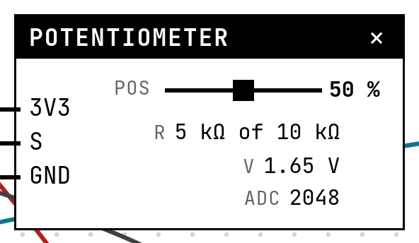
A potentiometer is a resistor with a third contact — the wiper — that slides along it. With the two ends on 3.3 V and ground, the wiper's voltage goes from 0 to 3.3 V as you turn the shaft: a voltage divider you can adjust. The chip's ADC turns that voltage into a number, 0 to 4095 on the ESP32.
In the simulator
The block has the wiper position as a slider (0 to 100 %; 0 % puts the wiper on the GND side) and shows what follows from it: the resistance between wiper and ground out of the total, the voltage, and the ADC count the code will read. The total resistance (1 kΩ to 100 kΩ) is a setting — it changes the numbers on the block, not the voltage, which is what a divider does.
Pins
| Pin | What it is |
|---|---|
| 3V3 | one end of the track — to a 3V3 symbol |
| S | the wiper — to a GPIO with an ADC (34 in the examples) |
| GND | the other end of the track — to a GND symbol |
Wiring
The circuit below is the example Servo on a potentiometer from the lab — open it with Project → Open example… and it comes ready to run.
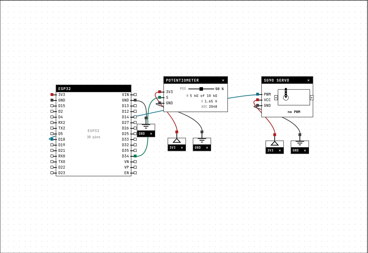
| Potentiometer pin | Goes to |
|---|---|
| 3V3 | a 3V3 symbol |
| S | D34 on the board (GPIO 34) |
| GND | a GND symbol |
Settings
Double-click the block's title bar to open its card, then the Settings tab. Changes apply to the running simulation right away.

| Setting | Accepts | Default | Notes |
|---|---|---|---|
| Total resistance | 1 kΩ · 5 kΩ · 10 kΩ · 50 kΩ · 100 kΩ | 10 kΩ | The value printed on the body of the part. The wiper splits that resistance. |
Code
#include <Arduino.h>
#include <ESP32Servo.h>

// The servo does not receive "degrees": it receives a PULSE of ~0.5 to 2.4 ms
// every 20 ms. write(angulo) only translates — the part shows the pulse measured.
Servo servo;
const int POT = 34, SINAL = 18;

void setup() {
  Serial.begin(115200);
  servo.attach(SINAL);
}

void loop() {
  int leitura = analogRead(POT);              // 0..4095
  int angulo = map(leitura, 0, 4095, 0, 180);
  servo.write(angulo);
  Serial.printf("pot=%4d -> %3d degrees\n", leitura, angulo);
  delay(100);
}analogRead(POT) returns 0–4095; map(value, 0, 4095, 0, 180) turns it into an angle for the servo. No pinMode is needed for an analog input.
Run it
Press Build and run. The first build of a project takes a while; after that, only what changed is rebuilt.
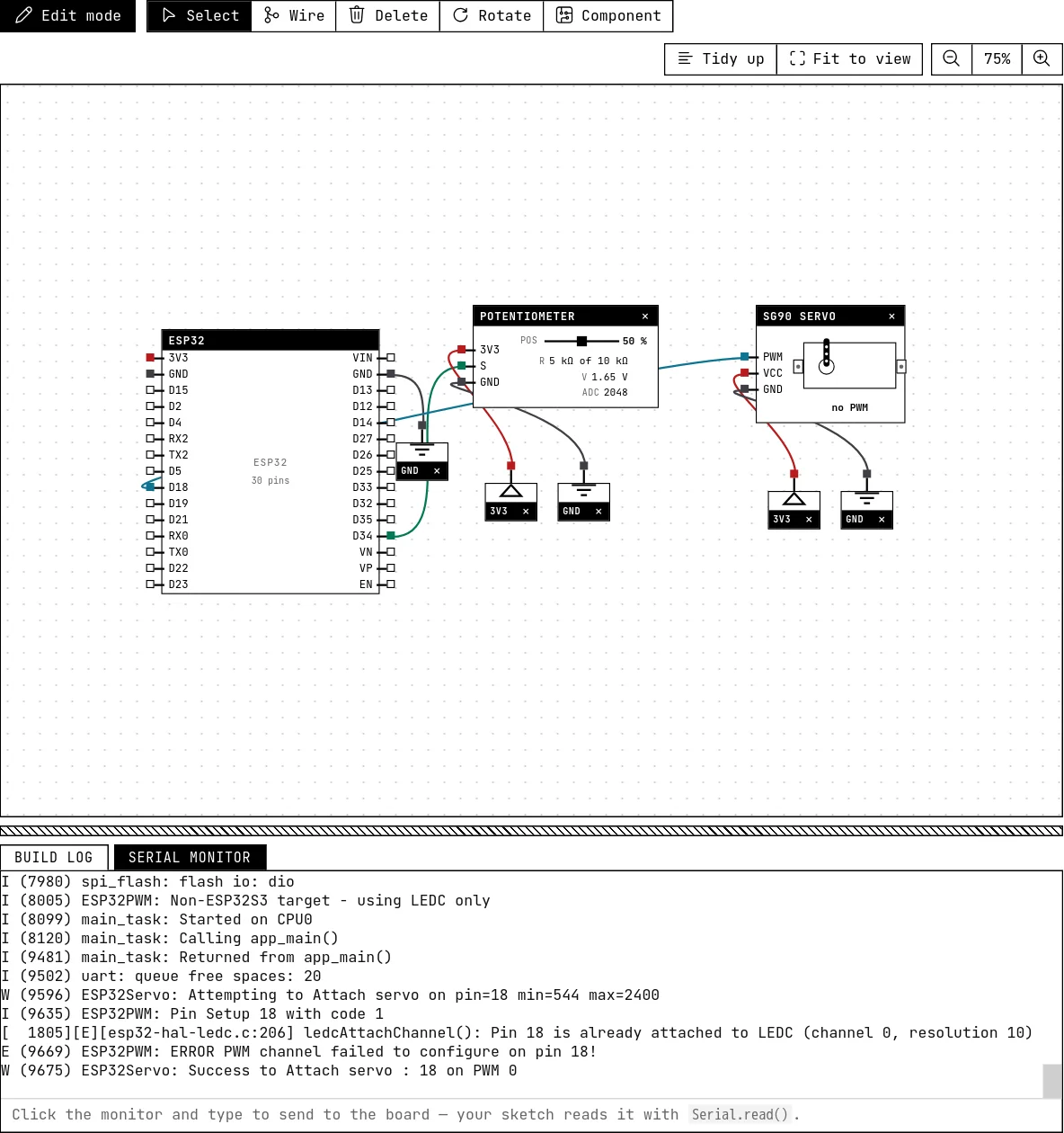
Drag the slider: the servo arm follows from 0° to 180° and the serial monitor prints the reading and the angle. Set the range to 10 kΩ or 100 kΩ in Settings and see the block's resistance line change while the ADC stays the same.
How the simulation models it
- The ADC count is linear with the position: 50 % gives 2048, 100 % gives 4095. The real ESP32 ADC is not perfectly linear and saturates a little before 3.3 V; that is not reproduced.
- The value is sent to the chip whenever the slider moves and again at start-up. There is no electrical noise: the reading is steady, unlike a real one that jitters by a few counts.
- The lab does not compute the divider from resistances — the block sets the ADC count directly from the position. The total resistance is informational.
Try this
- Print the reading as a voltage:
reading * 3.3 / 4095. - Average 16 readings before printing, and compare the steadiness with a single reading — then imagine the real, noisy sensor.
- Move the wiper wire to GPIO 5 and read the message the lab gives.
See also
- SG90 servo — A 9 g micro servo whose arm follows the width of the pulse it receives — the block shows the pulse it measures.
- LDR (photoresistor) — A resistor that drops with light — read through the ADC as a number that grows with brightness.
- Power, ground and the voltmeter — The GND and 3V3 symbols, the adjustable power supply, the voltmeter, and the electrical warnings the lab raises when a wire would damage the board.