Tutorials / Output
Color TFT display (ST7735 / ST7789)
The 7-pin SPI color screen in five sizes, from 80×160 to 240×320, with the quirks of the real controller — including the white screen of a wrong init.
- Color TFT display
What it is
The “7P SPI” TFT is one module in several sizes: 0.96″ 80×160, 1.44″ 128×128, 1.8″ 128×160 (ST7735 controllers) and 1.3″ 240×240, 2.4″ 240×320 (ST7789). All speak the same command set: set a window in the controller's memory, then pour pixels into it. Libraries such as Adafruit_ST7735 and Adafruit_ST7789 hide that behind drawPixel, fillRect and text.
In the simulator
The block shows the panel at the resolution of the model chosen in Settings. The simulation emulates the controller, so what appears is exactly the memory the firmware wrote — with the real module's habits: it boots asleep, obeys the datasheet's timing between reset and wake-up, and shows a white screen on TN glass (1.44″, 1.8″) or a black one on IPS glass when the initialization is wrong. Change the model in Settings and the constructor in the code must follow, or the drawing lands off the glass — as it does on the bench.
Pins
| Pin | What it is |
|---|---|
| GND | ground — to a GND symbol |
| 3V3 | power — to a 3V3 symbol |
| SCL | SPI clock — to GPIO 18 (VSPI) or 14 (HSPI) |
| SDA | SPI data (MOSI) — to GPIO 23 (VSPI) or 13 (HSPI) |
| RES | reset, active LOW — to a GPIO |
| DC | data/command select — to a GPIO |
| CS | chip select, active LOW — to a GPIO (or leave unconnected) |
| BLK | backlight — to 3V3, to a GPIO, or unconnected (see Settings) |
Wiring
The circuit below is the example Color display from the lab — open it with Project → Open example… and it comes ready to run.
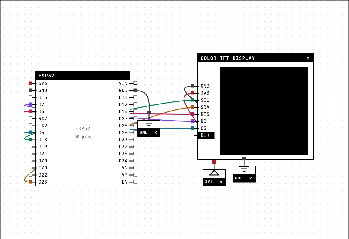
| Color TFT display pin | Goes to |
|---|---|
| GND | a GND symbol |
| 3V3 | a 3V3 symbol |
| SCL | D18 on the board (GPIO 18) |
| SDA | D23 on the board (GPIO 23) |
| RES | D4 on the board (GPIO 4) |
| DC | D2 on the board (GPIO 2) |
| CS | D5 on the board (GPIO 5) |
| BLK | left unconnected |
The clock pin decides the bus: SCL on GPIO 18 is VSPI, on GPIO 14 is HSPI, and SDA goes to the matching MOSI (23 or 13). DC and RES are ordinary GPIOs. The BLK pin depends on the module: the small 7P panels have a pull-up, so it may be left unconnected; the 1.44″ and 1.8″ need it on 3V3 or the backlight stays off.
Settings
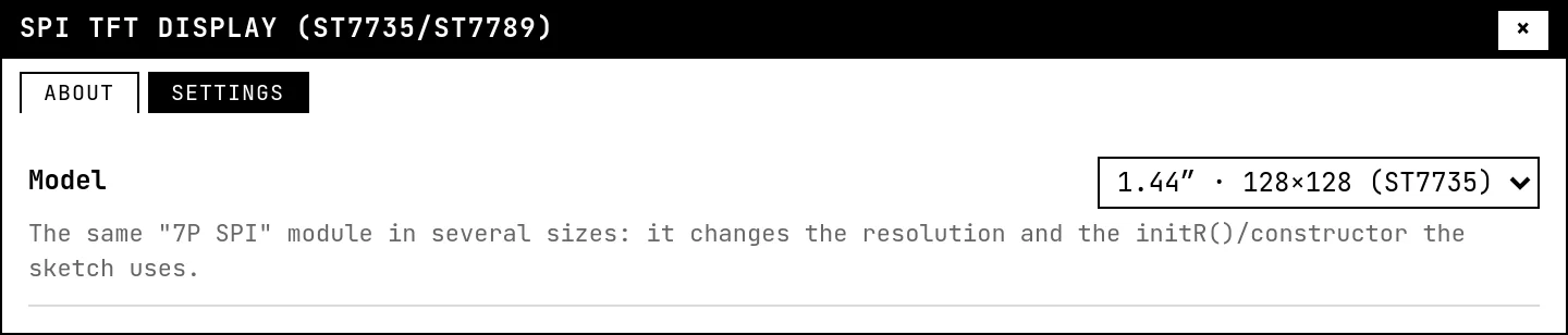
Double-click the block's title bar to open its card, then the Settings tab. Changes apply to the running simulation right away.
| Setting | Accepts | Default | Notes |
|---|---|---|---|
| Model | 0.96″ · 80×160 (ST7735S) · 1.44″ · 128×128 (ST7735) · 1.8″ · 128×160 (ST7735) · 1.3″ · 240×240 (ST7789) · 2.4″ · 240×320 (ST7789V) | 0.96″ · 80×160 (ST7735S) | The same "7P SPI" module in several sizes: it changes the resolution and the initR()/constructor the sketch uses. |
Code
This example deliberately uses no display library: it sends the controller's commands itself, so you can see what a library does for you — reset, sleep-out, pixel format, then CASET/RASET to open a window and RAMWR to fill it. The comments in the code explain each step. Adafruit_ST7735 works here just as well, and is what most sketches use.
// Color TFT display — painting the screen over SPI
//
// This is the code of the "Color display" example in the STANNUM gallery. It
// lives here, in docs/, and it is the SAME file the platform opens:
// templates.js imports it with ?raw. Editing it here changes what the student
// sees, and there is no second copy to drift apart.
//
// WHY THIS EXAMPLE TALKS TO THE DISPLAY BY HAND
// ---------------------------------------------
// Adafruit_ST7735 works here — it is the normal path, and it is what the
// datasheet card of the component teaches. This example exists for the other
// side: to show what the library hides. An SPI display is a memory where you
// open a window (CASET/RASET) and pour pixels into it (RAMWR); whoever gets
// this can read the datasheet of any controller in the family and is never
// held hostage by a library.
//
// If you only want to draw, use Adafruit: it is three lines and it takes care
// of fonts, shapes and rotation.
//
// THE WIRING (the same as the datasheet card, VSPI bus):
//   SCL -> GPIO18    SDA -> GPIO23    DC -> GPIO2
//   CS  -> GPIO5     RES -> GPIO4     VCC -> 3V3    GND -> GND
//
// Pick the panel model in the datasheet card of the block (double-click its
// bar). This code assumes the 1.44" one — 128x128. Changing the panel without
// changing the size here draws crooked, and that is what happens with the real
// module too.

#include <Arduino.h>
#include "driver/spi_master.h"
#include "driver/gpio.h"

#define PIN_SCL 18
#define PIN_SDA 23
#define PIN_DC   2
#define PIN_CS   5
#define PIN_RES  4

#define LARGURA 128
#define ALTURA  128

static spi_device_handle_t tela;

// The DC pin is what tells the display whether the byte is a COMMAND (0) or
// DATA (1). It is the central trick of this kind of bus: one single wire
// decides the meaning.
static void enviar(const uint8_t *bytes, int n, int dc) {
  gpio_set_level((gpio_num_t)PIN_DC, dc);
  spi_transaction_t t = {};
  t.length = n * 8;          // in BITS, not in bytes
  t.tx_buffer = bytes;
  spi_device_polling_transmit(tela, &t);
}

static void comando(uint8_t c)              { enviar(&c, 1, 0); }
static void dados(const uint8_t *b, int n)  { enviar(b, n, 1); }

// Opens the window where the next pixels will land. After RAMWR, every pair of
// bytes is one pixel, and the controller walks through the window on its own.
static void janela(int x0, int y0, int x1, int y1) {
  uint8_t c[4] = { 0, (uint8_t)x0, 0, (uint8_t)x1 };
  uint8_t r[4] = { 0, (uint8_t)y0, 0, (uint8_t)y1 };
  comando(0x2A); dados(c, 4);      // CASET: columns
  comando(0x2B); dados(r, 4);      // RASET: rows
  comando(0x2C);                   // RAMWR: "whatever comes now is pixel"
}

// Color in RGB565: 5 bits of red, 6 of green, 5 of blue, in a 16-bit integer.
// Green gets one extra bit because the human eye sees more shades of green.
static uint16_t cor(uint8_t r, uint8_t g, uint8_t b) {
  return ((r & 0xF8) << 8) | ((g & 0xFC) << 3) | (b >> 3);
}

static void pintar(uint16_t c) {
  janela(0, 0, LARGURA - 1, ALTURA - 1);
  // Send it in chunks: one transaction per pixel would be painfully slow, and
  // the whole buffer (32 KB) does not fit in a single SPI transaction.
  static uint8_t pedaco[64 * 2];
  for (int i = 0; i < 64; i++) {
    pedaco[i * 2]     = c >> 8;    // the controller expects the high byte first
    pedaco[i * 2 + 1] = c & 0xFF;
  }
  for (int n = 0; n < (LARGURA * ALTURA) / 64; n++) dados(pedaco, sizeof(pedaco));
}

void setup() {
  Serial.begin(115200);

  gpio_set_direction((gpio_num_t)PIN_DC, GPIO_MODE_OUTPUT);
  gpio_set_direction((gpio_num_t)PIN_RES, GPIO_MODE_OUTPUT);
  // Hardware reset: low, wait, high. The display needs this to start from a
  // known state.
  gpio_set_level((gpio_num_t)PIN_RES, 0); delay(20);
  gpio_set_level((gpio_num_t)PIN_RES, 1); delay(120);

  spi_bus_config_t barramento = {};
  barramento.mosi_io_num = PIN_SDA;
  barramento.miso_io_num = -1;       // the display only listens; nothing comes back
  barramento.sclk_io_num = PIN_SCL;
  barramento.quadwp_io_num = -1;
  barramento.quadhd_io_num = -1;
  barramento.max_transfer_sz = 4096;
  spi_bus_initialize(SPI3_HOST, &barramento, SPI_DMA_CH_AUTO);

  spi_device_interface_config_t dispositivo = {};
  dispositivo.clock_speed_hz = 10 * 1000 * 1000;   // 10 MHz
  dispositivo.mode = 0;
  dispositivo.spics_io_num = PIN_CS;
  dispositivo.queue_size = 4;
  spi_bus_add_device(SPI3_HOST, &dispositivo, &tela);

  comando(0x01); delay(150);                        // SWRESET: software reset
  comando(0x11); delay(120);                        // SLPOUT: wakes the panel up
  uint8_t formato = 0x05; comando(0x3A); dados(&formato, 1);  // COLMOD: 16 bits

  // MADCTL — the step almost every "by hand" tutorial forgets, and the one that
  // gives you a mirrored screen with red and blue swapped. The glass of these
  // modules comes mounted upside down and with the subpixels in BGR order;
  // 0xC8 (MX|MY|BGR) tells the controller to compensate for both. It is exactly
  // what Adafruit_ST7735 sends at rotation 0 — no magic, just the same math.
  uint8_t orientacao = 0xC8;
  comando(0x36); dados(&orientacao, 1);

  comando(0x29); delay(20);                         // DISPON: turns the image on

  Serial.println("display ready");
}

void loop() {
  struct { const char *nome; uint16_t valor; } cores[] = {
    { "red",    cor(255, 0, 0) },
    { "orange", cor(255, 140, 0) },
    { "yellow", cor(255, 220, 0) },
    { "green",  cor(0, 200, 80) },
    { "blue",   cor(0, 120, 255) },
    { "purple", cor(150, 0, 220) },
  };

  for (auto &c : cores) {
    pintar(c.valor);
    Serial.printf("painted %s\n", c.nome);
    delay(800);
  }
}
Run it
Press Build and run. The first build of a project takes a while; after that, only what changed is rebuilt.
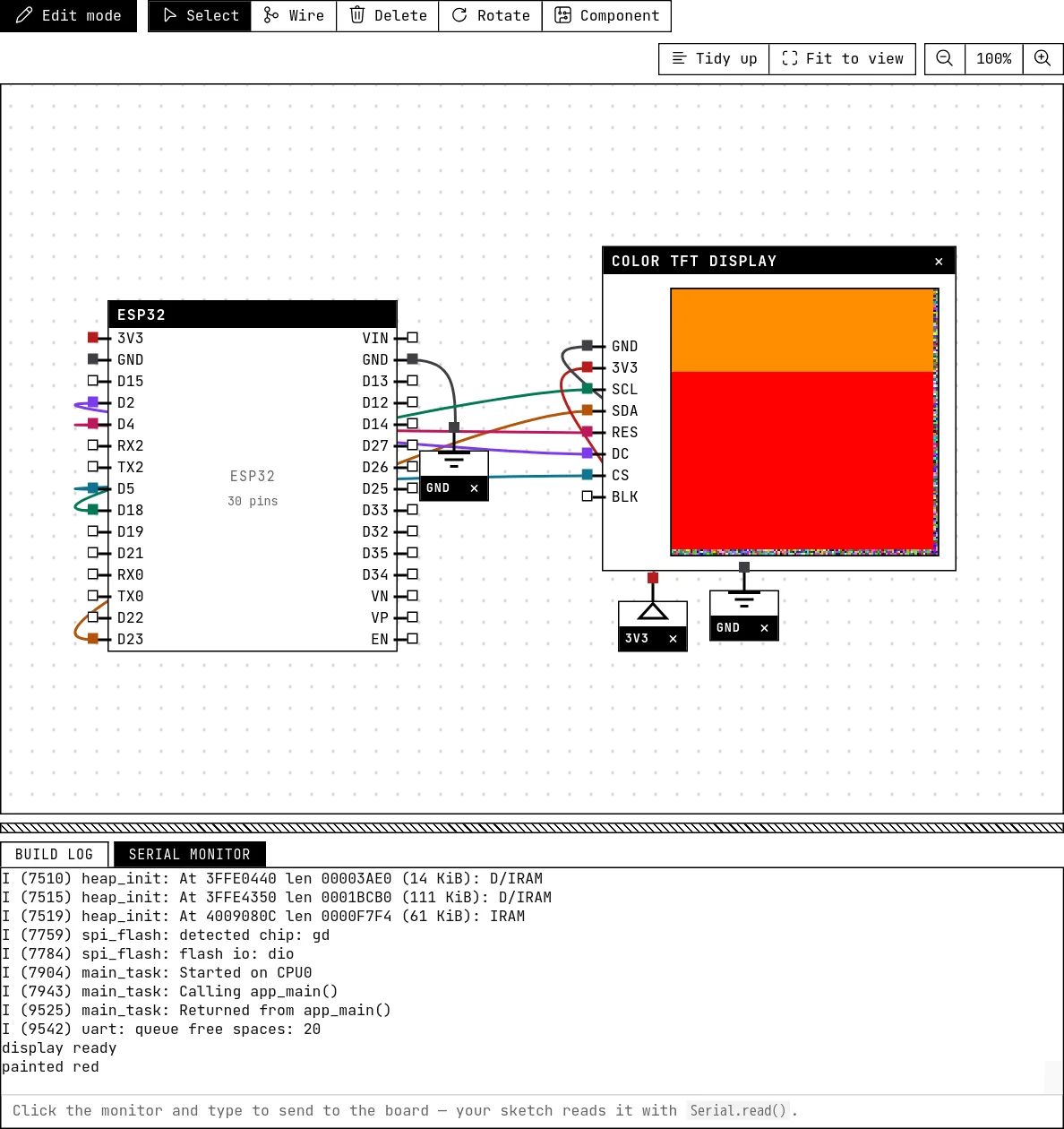
The 1.44″ panel changes color on its own, one full-screen fill after another. Open the build log: the simulation prints a line there whenever a command arrives too early after a reset, telling you why the screen stayed white.
How the simulation models it
- Emulated: the memory window (CASET/RASET/RAMWR), MADCTL rotation and mirroring with the offsets of each glass, 12/16/18-bit color, inversion, vertical scroll, sleep in/out, display on/off, software and hardware reset.
- Datasheet timing is enforced with a small margin: 5 ms of silence after a reset, 120 ms before SLPOUT is accepted, 120 ms for the panel to wake. A command sent too early is ignored and explained in the build log.
- The memory starts with noise, like the real chip at power-on, and a reset does not clear it — you see the snow until the sketch paints.
- One TFT per project. The 90°/270° rotations are approximate on non-square panels.
Try this
- Switch the model to 1.8″ in Settings without changing the code and see where the drawing goes; then fix the width and height in the sketch.
- Remove the
delay(120)after the reset and read the build log. - Replace the raw commands by
Adafruit_ST7735(add the libraryAdafruit ST7735 and ST7789 Library) and draw text.
See also
- OLED display (SSD1306) — The 0.96″ 128×64 screen on I²C: two wires, an address, and a library that draws text and shapes.
- Character LCD with I²C backpack — The classic 16×2 text display cut down to two wires by a small I²C board — text, custom characters and a backlight.
- ESP32 boards — Eight boards to choose from, pin by pin: which GPIOs reach the header, which are input-only, which have an ADC, and which must be left alone.