Tutorials / Power & measuring
Voltage divider and the voltmeter
A potentiometer as a divider on an ADC pin, with a voltmeter on the wiper: what the code reads, what the block shows, and what the meter can and cannot see.
- Potentiometer
- Voltmeter
What it is
A potentiometer is a resistor with a third terminal — the wiper — that slides along it. Wire the two ends to 3V3 and GND and the wiper is a voltage divider: at 50 % of the travel it sits at half the supply, 1.65 V. The ADC turns that voltage into a number from 0 to 4095, which is how every knob, slider and analog sensor reaches the code.
In the simulator
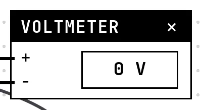
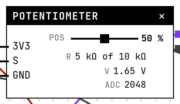
The potentiometer block shows the divider's arithmetic on its face: the wiper's position, the resistance on each side, the voltage at the wiper and the ADC count the code will read. The Voltmeter block sits across the wiper and ground. It is an instrument, not a part of the circuit: it shows the difference between its two probes and, in Settings, a Range — automatic, volts or millivolts, like a bench multimeter.
Pins
| Pin | What it is |
|---|---|
| + | the + probe — to the point you want to measure |
| − | the − probe — to the reference, usually a GND symbol |
Potentiometer
| Pin | What it is |
|---|---|
| 3V3 | the top of the divider — to a 3V3 symbol |
| S | the wiper, where the divided voltage comes out — to a GPIO with an ADC |
| GND | the bottom of the divider — to a GND symbol |
Wiring
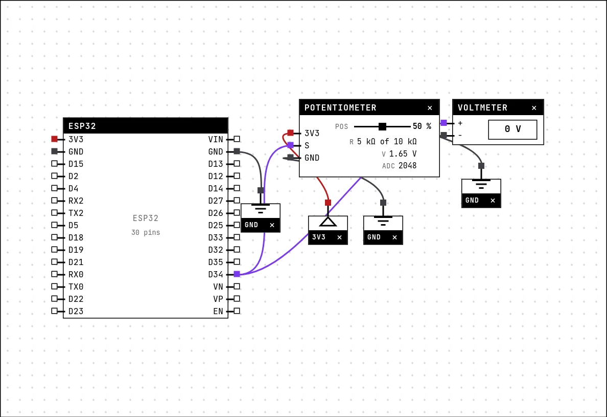
The circuit below is the example Voltage divider with a voltmeter from the lab — open it with Project → Open example… and it comes ready to run.
| Voltmeter pin | Goes to |
|---|---|
| + | D34 on the board (GPIO 34) |
| − | a GND symbol |
| Potentiometer pin | Goes to |
|---|---|
| 3V3 | a 3V3 symbol |
| S | D34 on the board (GPIO 34) |
| GND | a GND symbol |
The potentiometer's V and G go to a 3V3 and a GND symbol; its wiper S goes to GPIO 34, an input-only pin with an ADC. The voltmeter's + shares the wiper's net and its − goes to a GND symbol.
Settings
Double-click the block's title bar to open its card, then the Settings tab. Changes apply to the running simulation right away.

| Setting | Accepts | Default | Notes |
|---|---|---|---|
| Range | Automatic · Volts · Millivolts | Automatic | On the mV range, 3.3 V shows up as 3300 mV — handy to read small drops. |
Potentiometer

| Setting | Accepts | Default | Notes |
|---|---|---|---|
| Total resistance | 1 kΩ · 5 kΩ · 10 kΩ · 50 kΩ · 100 kΩ | 10 kΩ | The value printed on the body of the part. The wiper splits that resistance. |
Code
#include <Arduino.h>

const int ENTRADA = 34;            // GPIO 34: input only, with ADC
const float VREF = 3.3;

void setup() {
  Serial.begin(115200);
  delay(300);
  Serial.println("move the potentiometer wiper and compare with the voltmeter");
}

void loop() {
  int bruto = analogRead(ENTRADA);          // 0..4095
  float volts = bruto * VREF / 4095.0;
  float porcento = bruto * 100.0 / 4095.0;

  Serial.printf("ADC=%4d  %.2f V  (%.0f%% of travel)\n", bruto, volts, porcento);
  delay(400);
}
analogRead(34) gives 0 to 4095; multiplied by 3.3 and divided by 4095 it becomes volts, and by 100 it becomes the percentage of the travel. The sketch prints the three every 400 ms so you can compare them with the block's face.
Run it
Press Build and run. The first build of a project takes a while; after that, only what changed is rebuilt.
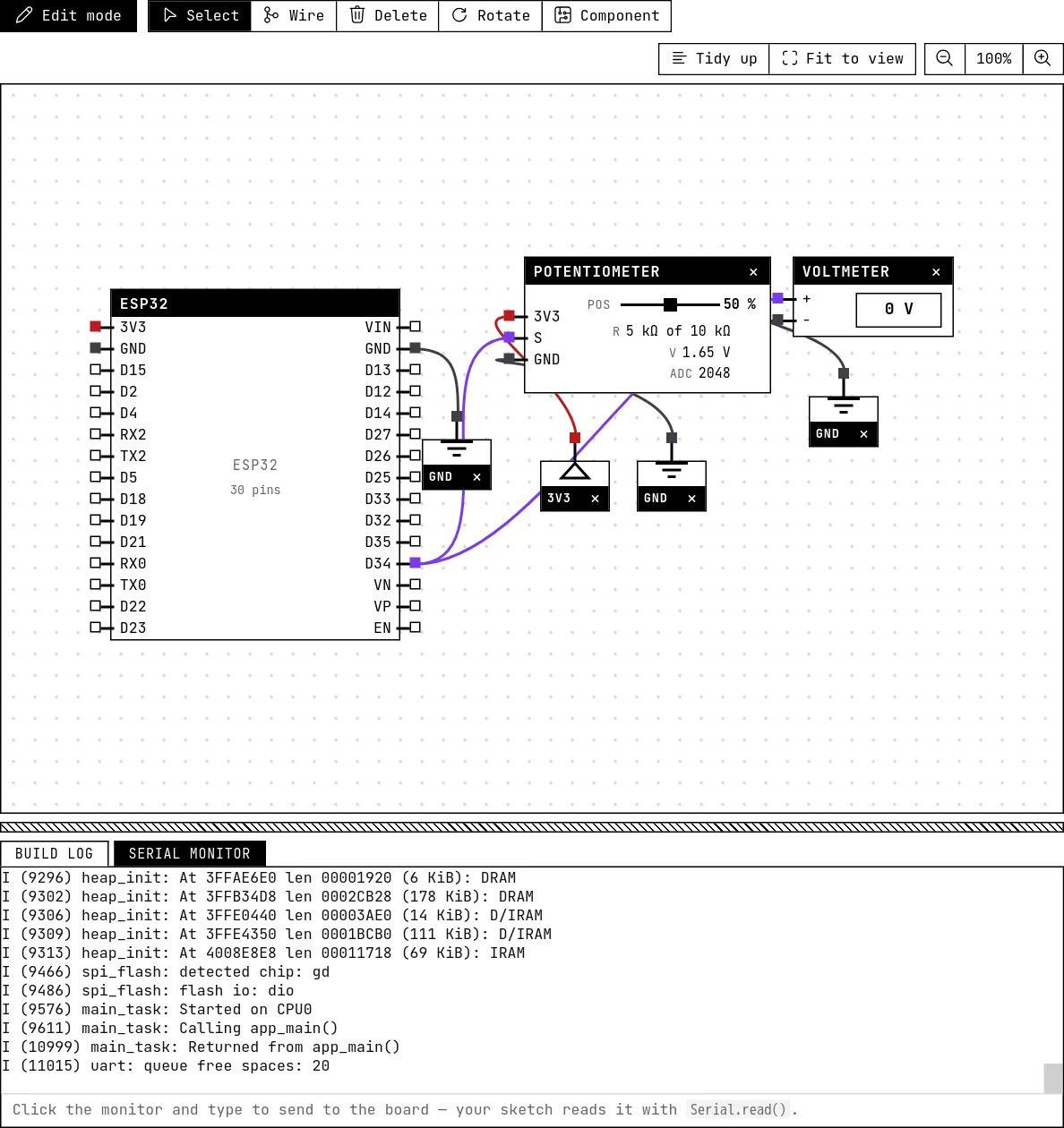
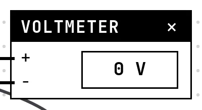
Drag the wiper: the ADC count, the volts and the percentage in the serial monitor follow the numbers on the potentiometer's face. The voltmeter, though, reads 0 V — hover it and the tooltip says its + probe is floating. That is not a bug; see below.
How the simulation models it
- The ADC count is 4095 × position, exactly, and the voltage on the block's face is 3.3 V × position. No noise, and none of the non-linearity a real chip's ADC has at the ends of the range.
- The voltmeter only sees potentials imposed by sources: the 3V3 and GND nets, the power supply block, the board's power pins and the GPIOs the firmware drives. The lab does not solve resistor networks, so the wiper's net has no potential of its own — the potentiometer computes the divided voltage itself and shows it on its face, and the meter across the wiper sees a floating probe. Move the + probe to the potentiometer's V pin and the meter reads 3.3 V.
- Because the voltage is arithmetic and the meter is about levels, this example is really about the conversion — count, volts, position — which is the first thing to get wrong on a bench.
Try this
- Move the voltmeter's + probe to the potentiometer's V pin (the 3V3 side): it reads 3.3 V. Switch the Range to mV.
- Change
VREFin the code to 3.0 and watch the printed volts stop matching the block — the mistake of assuming a supply that is not there. - Wire the wiper to GPIO 22 instead of 34 and build: the lab tells you the pin has no ADC.
See also
- Power, ground and the voltmeter — The GND and 3V3 symbols, the adjustable power supply, the voltmeter, and the electrical warnings the lab raises when a wire would damage the board.
- Potentiometer — A variable resistor whose wiper divides 3.3 V — the first analog input, read with analogRead().
- ESP32 boards — Eight boards to choose from, pin by pin: which GPIOs reach the header, which are input-only, which have an ADC, and which must be left alone.