Tutorials / Output
Character LCD with I²C backpack
The classic 16×2 text display cut down to two wires by a small I²C board — text, custom characters and a backlight.
- I²C LCD
- LM35
What it is
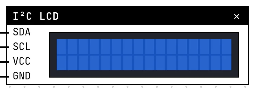
The HD44780 LCD shows characters, not pixels: 16 columns by 2 rows in the usual module (20×4 also exists). It normally needs six data wires; the I²C backpack — a PCF8574 expander soldered to the back — turns that into SDA and SCL. The price is an address you must get right: 0x27 on most backpacks, 0x3F on the PCF8574A variant.
In the simulator
The block shows the glass with each character drawn dot by dot, in blue-with-white or green-with-black glass, with the cursor and the backlight the code controls. Settings: the address, the size (16×2, 20×4, 16×4) and the glass color. If the display lights up but stays blank, it is the address — the same symptom as on the bench.
Pins
| Pin | What it is |
|---|---|
| SDA | I²C data — to a GPIO |
| SCL | I²C clock — to a GPIO |
| VCC | power — to a 3V3 symbol |
| GND | ground — to a GND symbol |
Wiring
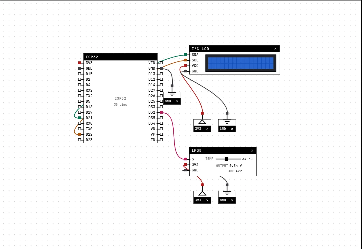
The circuit below is the example Thermometer on the I²C LCD from the lab — open it with Project → Open example… and it comes ready to run.
| I²C LCD pin | Goes to |
|---|---|
| SDA | D21 on the board (GPIO 21) |
| SCL | D22 on the board (GPIO 22) |
| VCC | a 3V3 symbol |
| GND | a GND symbol |
Settings
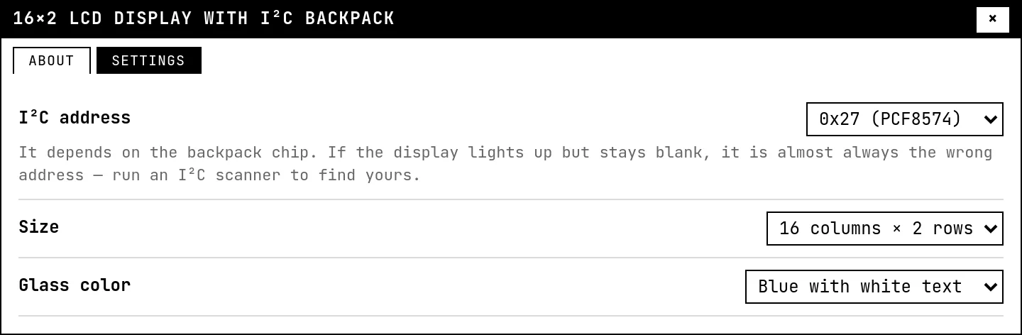
Double-click the block's title bar to open its card, then the Settings tab. Changes apply to the running simulation right away.
| Setting | Accepts | Default | Notes |
|---|---|---|---|
| I²C address | 0x27 (PCF8574) · 0x3F (PCF8574A) | 0x27 (PCF8574) | It depends on the backpack chip. If the display lights up but stays blank, it is almost always the wrong address — run an I²C scanner to find yours. |
| Size | 16 columns × 2 rows · 20 columns × 4 rows · 16 columns × 4 rows | 16 columns × 2 rows | |
| Glass color | Blue with white text · Green with black text | Blue with white text |
Code
#include <Arduino.h>
#include <Wire.h>
#include <LiquidCrystal_I2C.h>

// address, columns, rows. If it lights up but writes nothing, it is almost
// always the address: modules ship as 0x27 (PCF8574) or 0x3F (PCF8574A).
LiquidCrystal_I2C lcd(0x27, 16, 2);
const int LM35 = 32;

// The HD44780 lets you draw 8 characters of your own: 8 rows of 5 dots
// each. This one is the degree symbol.
byte grau[8] = {0b01100,0b10010,0b10010,0b01100,0b00000,0b00000,0b00000,0b00000};

void setup() {
  Serial.begin(115200);
  Wire.begin(21, 22);        // SDA, SCL — any GPIOs work on the ESP32
  lcd.init();
  lcd.backlight();
  lcd.createChar(0, grau);
  lcd.setCursor(0, 0);
  lcd.print("Thermometer");
  delay(1200);
  lcd.clear();
}

void loop() {
  float t = analogRead(LM35) * 330.0 / 4095;   // 10 mV per degree

  lcd.setCursor(0, 0);
  lcd.print("Temp: ");
  lcd.print(t, 1);
  lcd.write((byte)0);        // the degree symbol I drew
  lcd.print("C   ");

  // 16-block level bar: 0 to 50 degrees
  int blocos = constrain(map((int)t, 0, 50, 0, 16), 0, 16);
  lcd.setCursor(0, 1);
  for (int i = 0; i < 16; i++) lcd.write(i < blocos ? (char)255 : ' ');

  Serial.printf("%.1f C -> %d blocks\n", t, blocos);
  delay(500);
}The LiquidCrystal I2C library: init(), backlight(), setCursor(col, row), print(). The example also draws its own degree symbol with createChar() — the controller stores up to 8 custom 5×8 characters — and fills the second row with block characters as a level bar for the LM35 reading.
Run it
Press Build and run. The first build of a project takes a while; after that, only what changed is rebuilt.
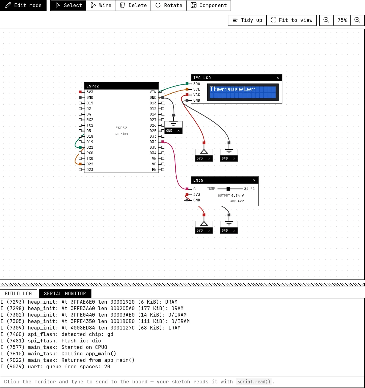
The first row shows the temperature with the custom degree symbol; the second row is a bar that grows as you drag the LM35's slider. Call noBacklight() and the glass darkens but the text stays — an LCD does not emit light, it only blocks it.
How the simulation models it
- The simulation emulates the PCF8574 and the HD44780 behind it: every byte the library writes becomes the state of the expander's pins, and the controller latches nibbles on the falling edge of E, as the datasheet says. Commands (clear, home, cursor, entry mode, display shift), DDRAM and CGRAM are all there.
- The address must match, and the module only joins the bus with both SDA and SCL wired.
- The 80-character DDRAM and its non-contiguous row layout are reproduced: text written past column 16 lands where a real module would put it.
Try this
- Scroll a long message across the first row with
scrollDisplayLeft()every 300 ms. - Switch the size to 20×4 in Settings and in the constructor, and use the four rows for four sensors.
See also
- OLED display (SSD1306) — The 0.96″ 128×64 screen on I²C: two wires, an address, and a library that draws text and shapes.
- LM35 temperature sensor — Ten millivolts per degree, straight from the sensor: read the voltage, multiply by 100.