Tutorials / Input
Slide switch
A contact that stays where you leave it — on/off state, read like a button.
- Switch
- LED
What it is
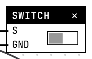
A slide switch is the button's steady cousin: it has two positions and keeps the last one. Electrically it is the same contact between a GPIO and ground, read with the internal pull-up.
In the simulator
The block shows the slider; click it to toggle. Its position is part of the project — it is saved and comes back when the project is opened, like the position of a real switch on a board.
Pins
| Pin | What it is |
|---|---|
| S | signal — to a GPIO configured as an input |
| GND | the other side of the contact — to a GND symbol |
Wiring
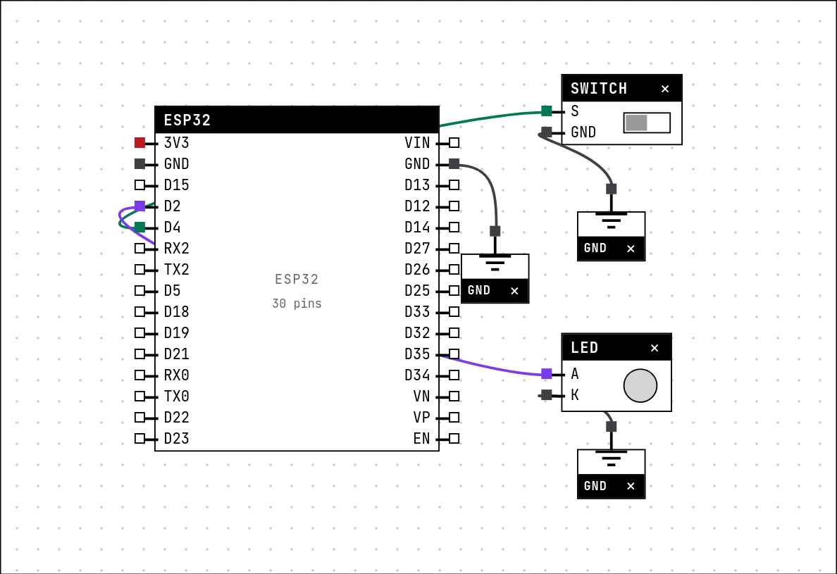
Build this circuit yourself: start a New project, add the parts from the catalog and wire them as in the table.
| Switch pin | Goes to |
|---|---|
| S | D4 on the board (GPIO 4) |
| GND | a GND symbol |
Settings
Double-click the block's title bar to open its card, then the Settings tab. Changes apply to the running simulation right away.

| Setting | Accepts | Default | Notes |
|---|---|---|---|
| Contact | Normally open (NA) · Normally closed (NF) | Normally open (NA) |
Code
#include <Arduino.h>

// A slide switch has a STATE: it stays where you left it. With the contact
// wired to GND and the internal pull-up on, the pin reads LOW while the
// switch is closed and HIGH while it is open.
const int SWITCH = 4;
const int LED = 2;

void setup() {
  Serial.begin(115200);
  pinMode(SWITCH, INPUT_PULLUP);
  pinMode(LED, OUTPUT);
}

void loop() {
  bool closed = digitalRead(SWITCH) == LOW;
  digitalWrite(LED, closed ? HIGH : LOW);
  Serial.println(closed ? "switch closed - LED on" : "switch open - LED off");
  delay(500);
}
Identical to the button: INPUT_PULLUP and digitalRead() == LOW for closed. The sketch copies the state to an LED and prints it twice a second.
Run it
Press Build and run. The first build of a project takes a while; after that, only what changed is rebuilt.
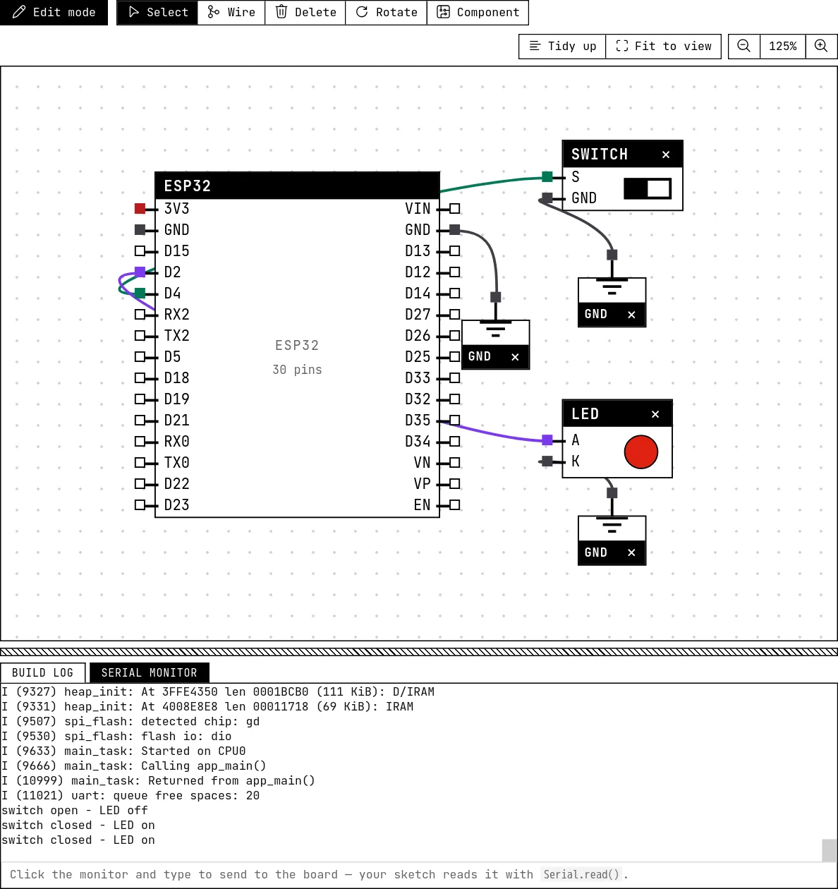
Click the switch: the LED follows and the serial monitor changes from “switch open” to “switch closed”. Click again to open it.
How the simulation models it
- The block drives the level of its pin: HIGH while open, LOW while closed for a normally-open contact (the Contact setting inverts it).
- The state is sent to the simulation at start-up, so a sketch that reads the switch in
setup()sees the position it was left in.
Try this
- Use the switch as a mode selector: closed, the LED blinks fast; open, it blinks slowly.
- Print the state only when it changes, not every half second.
See also
- Push button — A momentary contact: HIGH while released, LOW while pressed — the first digital input.
- Reed switch — A contact that closes near a magnet — the sensor on every door and window alarm.