Tutorials / Sensors
Soil moisture and rain sensors
Two resistive boards with the same electronics: a dry board reads HIGH, and a comparator gives a digital alarm.
- Soil moisture
- Rain sensor
- Relay
- AC supply
- Lamp
What it is
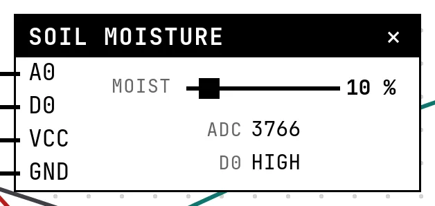
The soil hygrometer (YL-69) is a two-prong fork; the rain sensor (FC-37) is a board of interlaced tracks. Both measure how well water conducts between two electrodes and come with the same little comparator board as the MQ-2. The thing to remember about both: dry reads HIGH — the wetter, the lower the number.
In the simulator
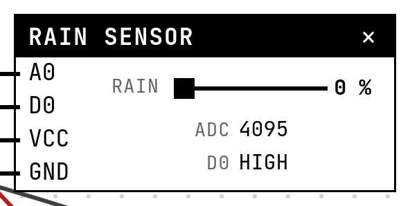
Each block has one slider — Moist for the soil, Rain for the board — and shows the ADC count and D0. The threshold and the polarity of D0 are in Settings. The example uses both to decide whether to water: dry soil and no rain.
Pins
| Pin | What it is |
|---|---|
| A0 | A0, the analog reading — to a GPIO with an ADC |
| D0 | D0, the comparator's output — to a GPIO (optional) |
| VCC | power — to a 3V3 symbol |
| GND | ground — to a GND symbol |
Rain sensor
| Pin | What it is |
|---|---|
| A0 | A0, the analog reading — to a GPIO with an ADC |
| D0 | D0, the comparator's output — to a GPIO (optional) |
| VCC | power — to a 3V3 symbol |
| GND | ground — to a GND symbol |
Wiring
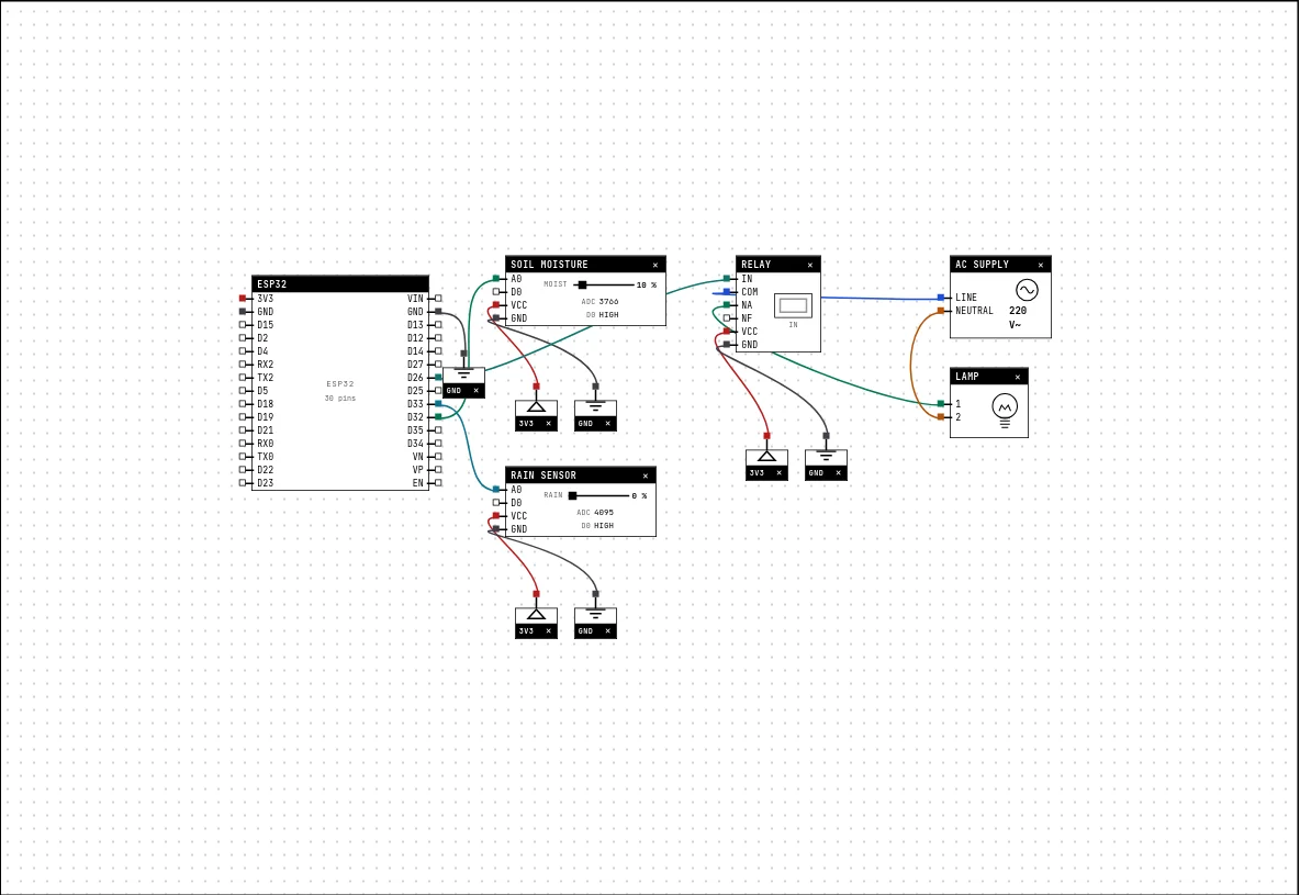
The circuit below is the example Automatic irrigation — soil + rain from the lab — open it with Project → Open example… and it comes ready to run.
| Soil moisture pin | Goes to |
|---|---|
| A0 | D32 on the board (GPIO 32) |
| D0 | left unconnected |
| VCC | a 3V3 symbol |
| GND | a GND symbol |
| Rain sensor pin | Goes to |
|---|---|
| A0 | D33 on the board (GPIO 33) |
| D0 | left unconnected |
| VCC | a 3V3 symbol |
| GND | a GND symbol |
Settings
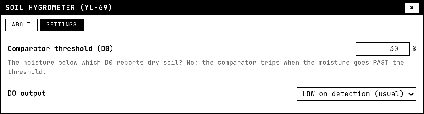
Double-click the block's title bar to open its card, then the Settings tab. Changes apply to the running simulation right away.
| Setting | Accepts | Default | Notes |
|---|---|---|---|
| Comparator threshold (D0) | 0 to 100 % | 30 % | The moisture below which D0 reports dry soil? No: the comparator trips when the moisture goes PAST the threshold. |
| D0 output | LOW on detection (usual) · HIGH on detection | LOW on detection (usual) |
Rain sensor
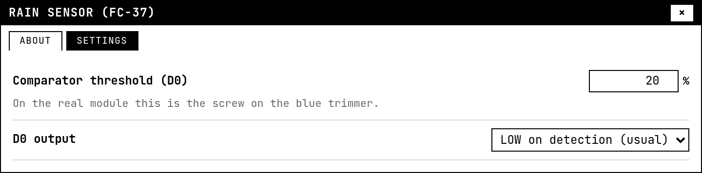
| Setting | Accepts | Default | Notes |
|---|---|---|---|
| Comparator threshold (D0) | 0 to 100 % | 20 % | On the real module this is the screw on the blue trimmer. |
| D0 output | LOW on detection (usual) · HIGH on detection | LOW on detection (usual) |
Code
#include <Arduino.h>

// Remember the INVERTED signal of these resistive sensors:
// DRY soil reads HIGH; a DRY rain board reads HIGH.
const int SOLO = 32, CHUVA = 33, BOMBA = 26;
const int SOLO_SECO = 3000;      // above this the pot is asking for water
const int CHOVENDO = 3000;       // below this there is water on the board

void setup() {
  Serial.begin(115200);
  pinMode(BOMBA, OUTPUT);
}

void loop() {
  int solo = analogRead(SOLO);
  int chuva = analogRead(CHUVA);
  bool seco = solo > SOLO_SECO;
  bool chovendo = chuva < CHOVENDO;

  // watering in the rain is a waste: BOTH sensors decide
  bool regar = seco && !chovendo;
  digitalWrite(BOMBA, regar);

  Serial.printf("soil=%4d%s rain=%4d%s -> pump %s\n",
                solo, seco ? " (dry)" : "", chuva, chovendo ? " (raining)" : "",
                regar ? "ON" : "stopped");
  delay(500);
}
Two analogRead calls with the inverted logic spelled out: seco = solo > 3000, chovendo = chuva < 3000. The pump (a relay with a lamp standing in for it) runs only when seco && !chovendo.
Run it
Press Build and run. The first build of a project takes a while; after that, only what changed is rebuilt.
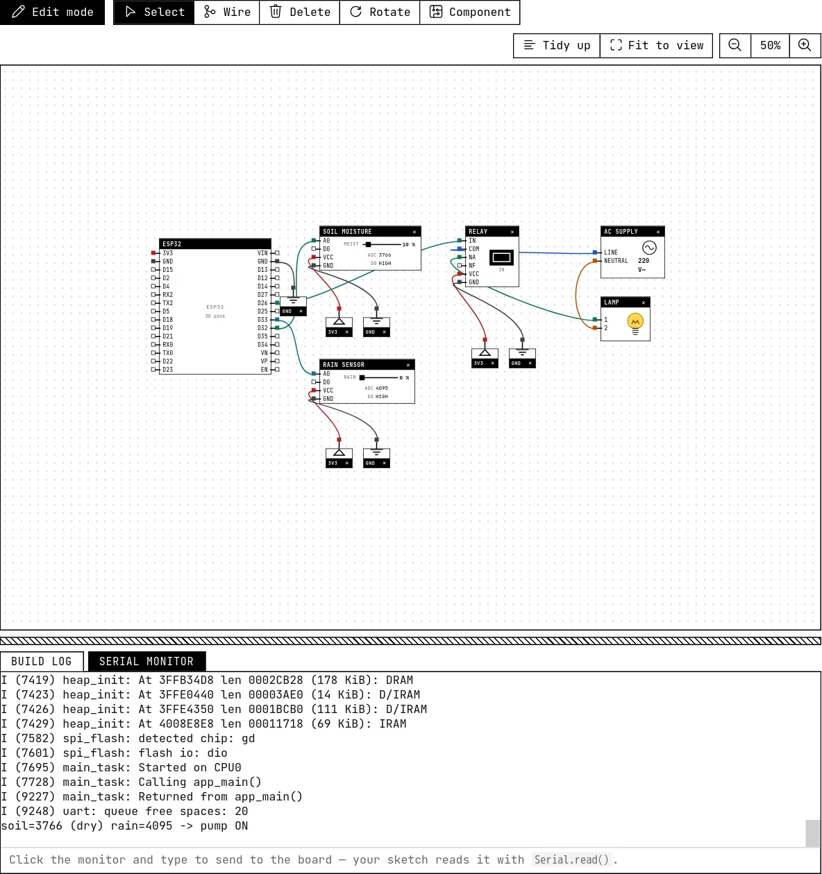
With the soil slider low and no rain, the relay is on and the lamp lights. Raise the moisture, or make it rain, and the pump stops — the serial monitor prints both readings and the decision.
How the simulation models it
- Soil: ADC = 4095 − slider × (4095 − 800), from 4095 bone-dry to 800 soaked. Rain: ADC = 4095 − slider × (4095 − 600).
- D0 trips when the slider passes the threshold (30 % for soil, 20 % for rain by default), with the polarity from Settings.
- Both sensors corrode on a bench when powered continuously; the usual advice — power them only during the reading — has no effect here, but keep the habit.
Try this
- Add hysteresis to the pump: start below one moisture, stop above a higher one.
- Log a line per minute with both readings and the pump state, ready for a spreadsheet.
See also
- MQ-2 gas and smoke sensor — An analog reading that rises with gas, plus a digital alarm output with a threshold you set on the module.
- Relay, lamp and the mains — The electromechanical switch that lets a 3.3 V pin drive a lamp on the mains — with the AC side kept away from the board.
- LDR (photoresistor) — A resistor that drops with light — read through the ADC as a number that grows with brightness.