Tutorials / Getting started
Your first circuit: blink an LED
From an empty canvas to a blinking LED — placing a part, drawing wires, writing the code, saving and running. Ten minutes, and you will have used every part of the lab once.
This walkthrough builds the smallest complete project there is: one LED, two wires and a sketch that turns it on and off. Every screenshot is the real lab, so what you see here is what you will see on your screen. Open the simulator in another tab and follow along.
01 Meet the lab
The lab has three areas. On the left, the files of your project and the code editor. On the right, the canvas where the circuit is drawn — the board is already there, because every project has one. Below the canvas, the output panel: the build log and the serial monitor. The buttons at the top run and stop the simulation and open the menus.
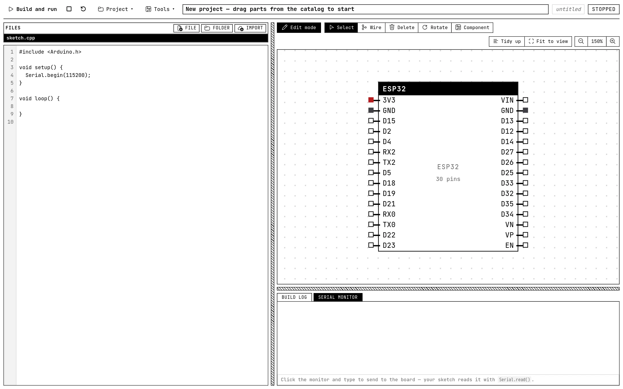
If you have something on the canvas already, choose Project → New project to start from a clean board.
02 Add an LED
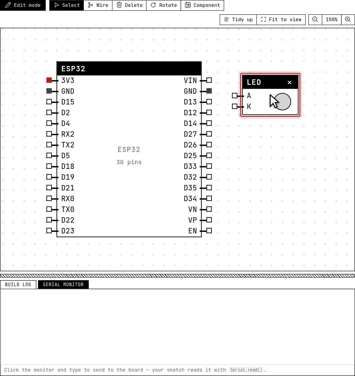
Parts come from the catalog: the Component button in the canvas toolbar. Click it and the catalog opens; there is a search box at the top if the list is long.
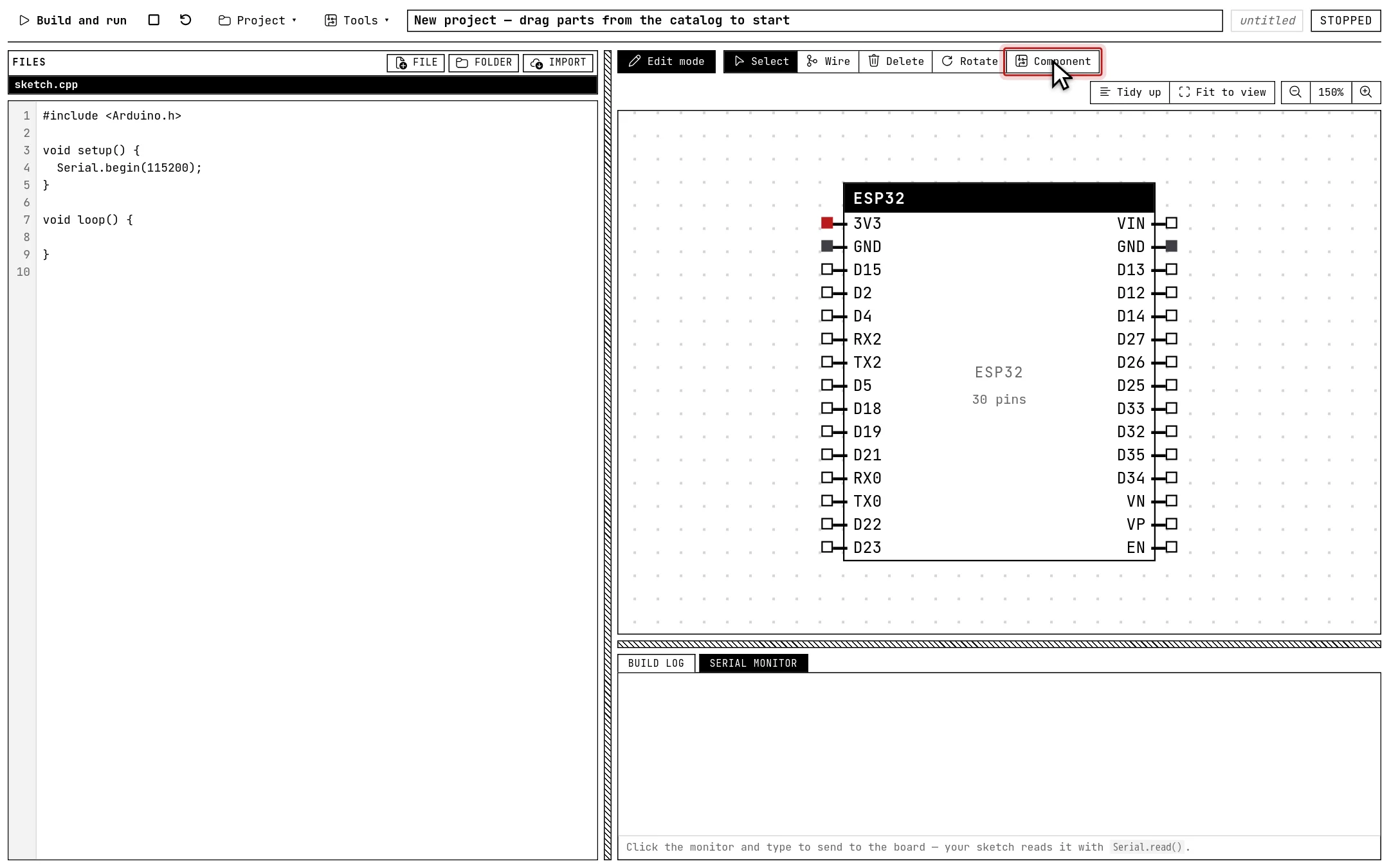
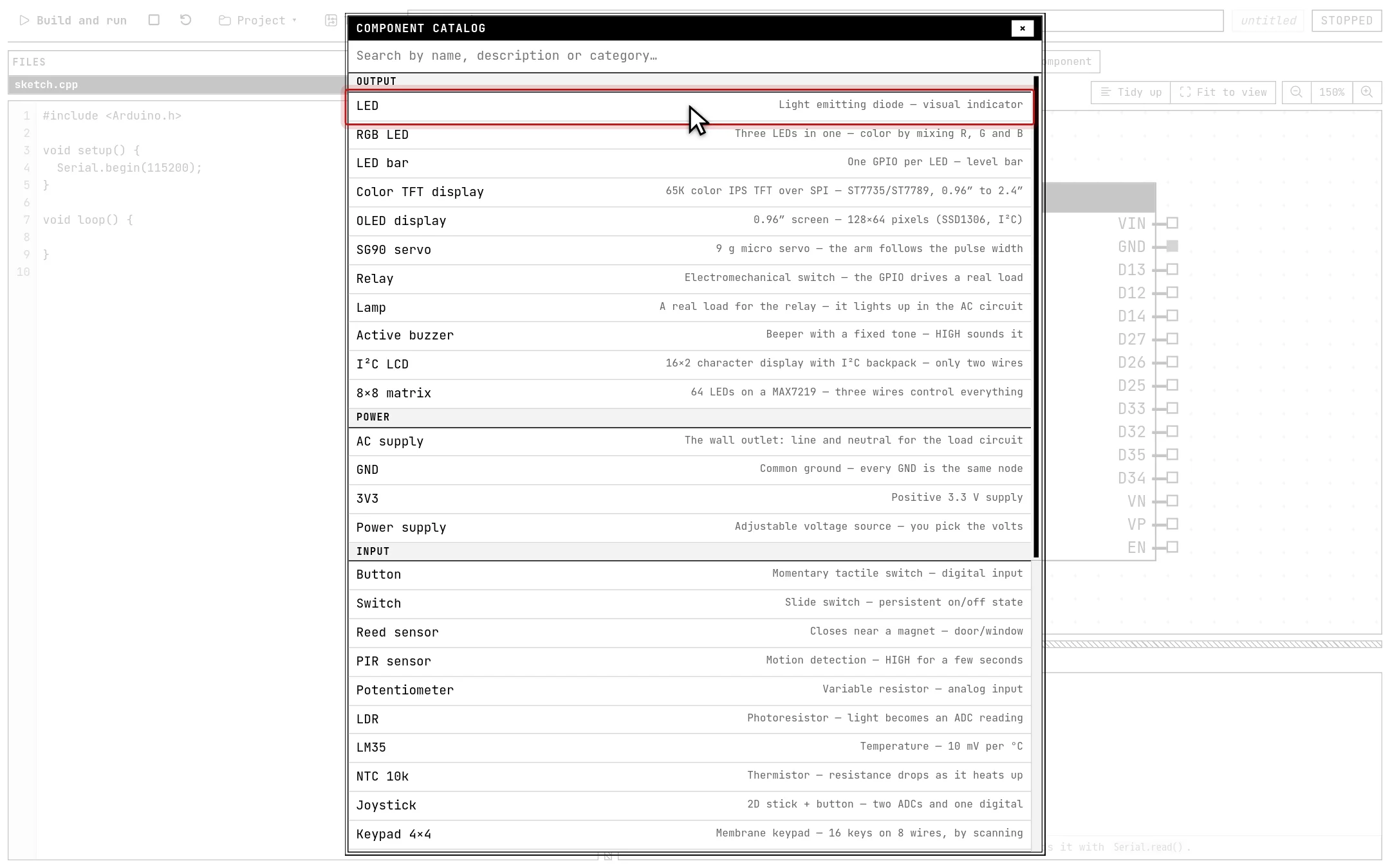
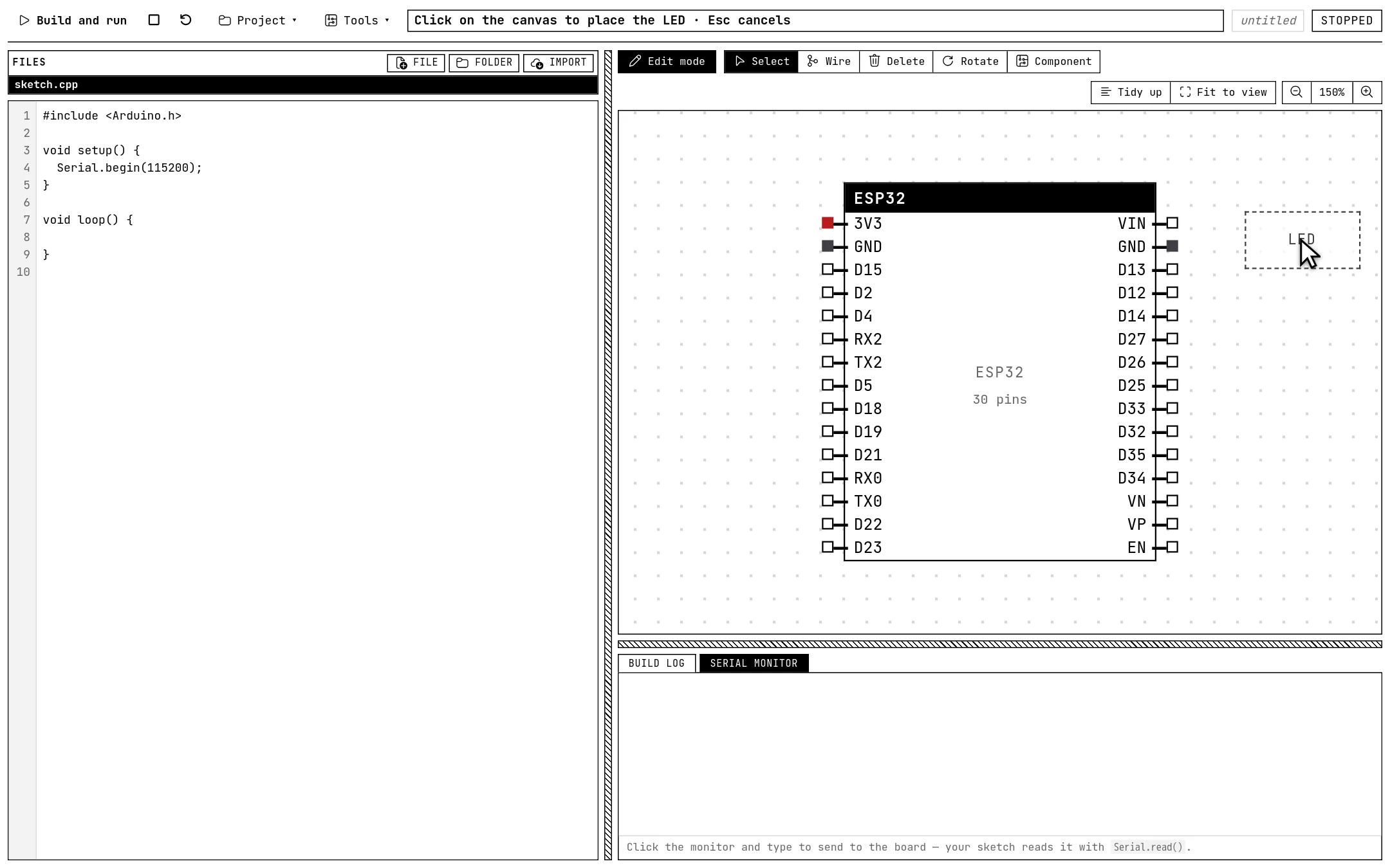
When you click a part, it sticks to the cursor. Move over the canvas and click where you want it — to the right of the board, with some room around it for the wires. Esc cancels if you change your mind.
03 Wire the LED to the board
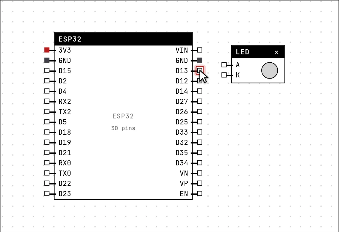
Select the Wire tool in the canvas toolbar. With it, a click on a pin starts a wire and the next click on another pin finishes it.

Click pin D13 on the right side of the board. The pin lights up: the wire has started, and it follows the cursor.
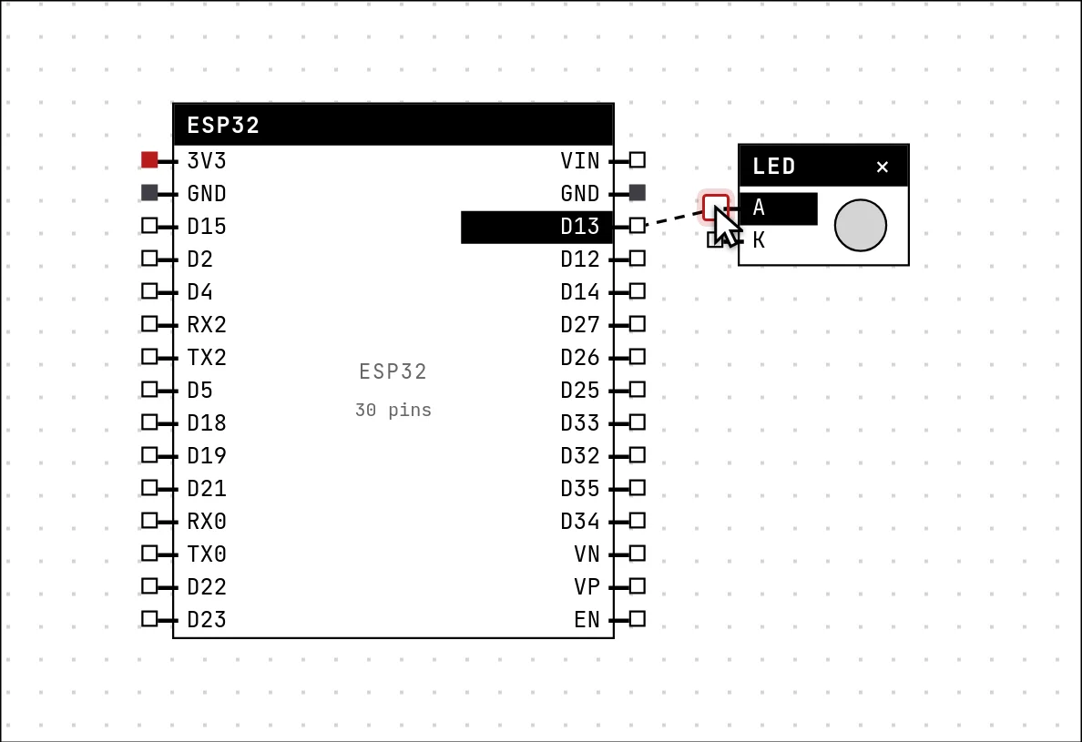
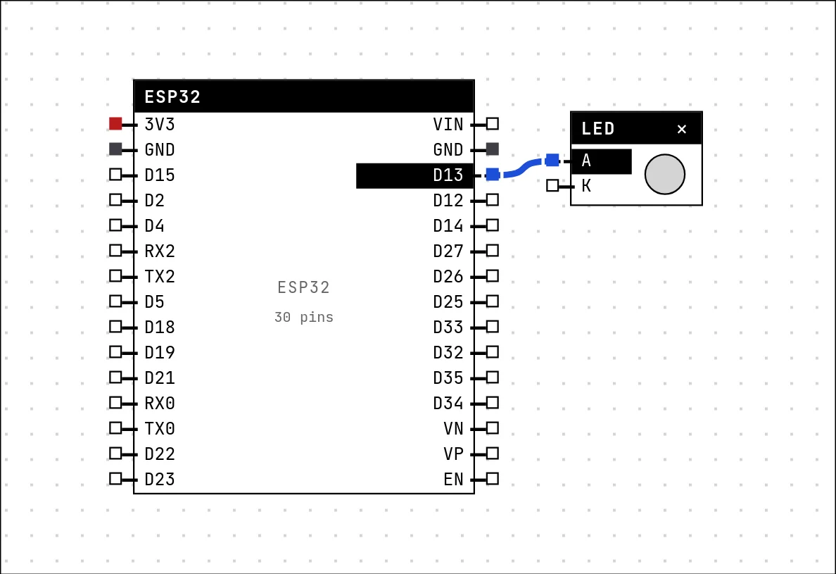
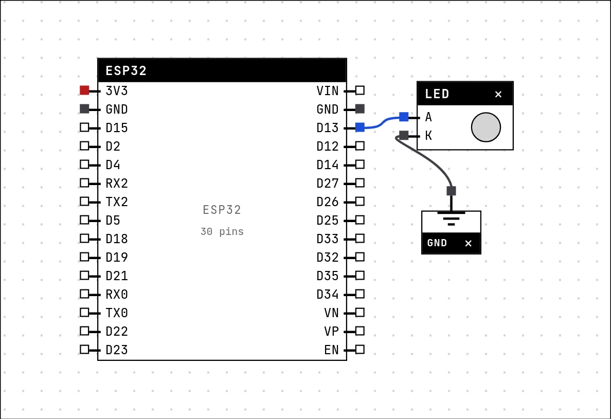
Now click A on the LED — the anode, the leg that receives current. The wire is drawn, and both pins take the color of the wire: they are on the same electrical net now.
04 Close the circuit with a ground symbol
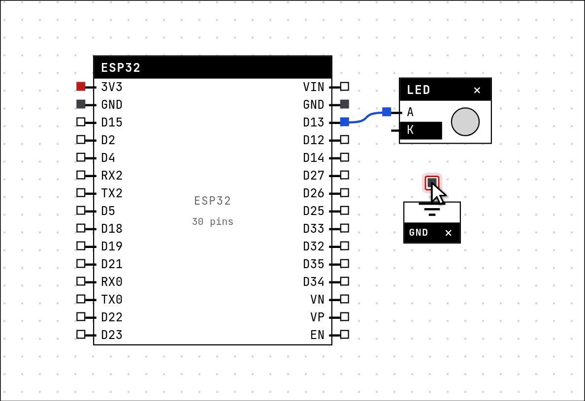
Current needs a way back. In the lab, ground is a symbol: every GND symbol on the canvas is the same node, exactly like the ground symbol in a schematic. Open the catalog again (switch back to the Select tool first, or press Esc), pick GND and drop it under the LED.
Then, with the Wire tool, connect the LED's K (the cathode, the short leg) to the ground symbol.
05 Write the code
Click in the editor and replace what is there with the sketch below. pinMode() makes GPIO 13 an output; loop() turns it on and off every half second and prints a line each time.
#include <Arduino.h>

const int LED = 13;

void setup() {
  Serial.begin(115200);
  pinMode(LED, OUTPUT);
}

void loop() {
  digitalWrite(LED, HIGH);
  Serial.println("LED on");
  delay(500);
  digitalWrite(LED, LOW);
  Serial.println("LED off");
  delay(500);
}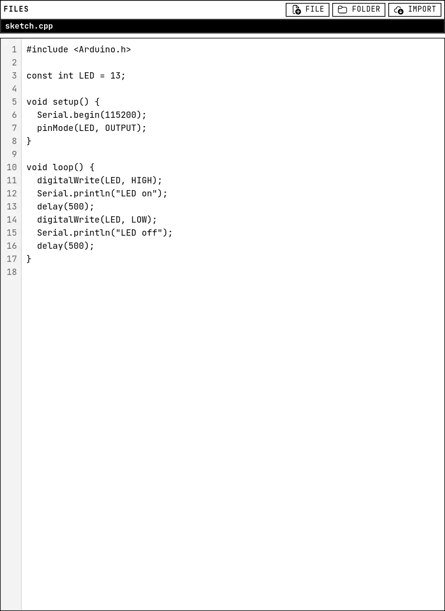
Note that the code talks about GPIO 13 and the wire goes to D13: the label on the board is the GPIO number with a “D” in front. If the number in the code and the pin on the canvas do not match, the LED simply will not blink — the most common mistake of a first project.
06 Save the project
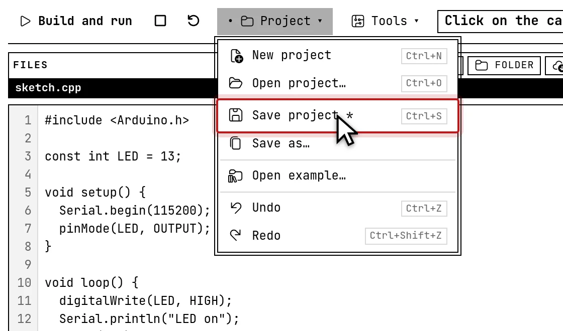
Project → Save project (or Ctrl+S). The first time, the lab asks for a name. Saving does two things at once: it keeps the project in this browser, so it shows up under Open project…, and it downloads a .zip — your code as .cpp files plus the circuit — the copy you can keep, e-mail or open on another computer.

07 Build and run
Press Build and run. Your code is compiled for real — the same compiler a physical board would use — and then loaded into an emulated chip. The status on the right goes Building, then Starting, then Running. A first build takes a while; the next ones only rebuild what changed.

Running: the LED on the canvas blinks in step with the firmware, and every Serial.println lands in the serial monitor below the canvas. This is your code executing, not an animation of what it should do.
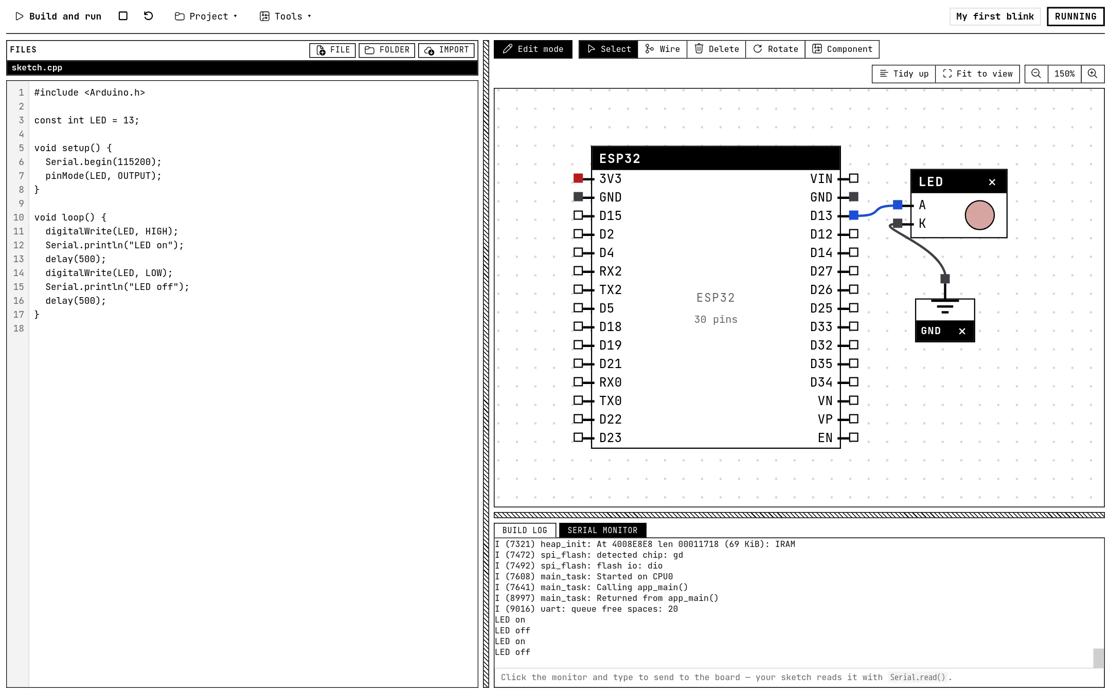
Change delay(500) to delay(100) and press Build and run again: the LED blinks five times faster. That loop — edit, run, watch — is the whole method.
What you just used
- The catalog and placing a part (Placing parts and wiring goes deeper: junctions, free tracks, moving and deleting).
- The Wire tool and the idea of a net: pins joined by wires share a color and a potential; GND symbols are all one net.
- The editor, and the rule that the GPIO in the code must match the pin on the canvas.
- Save, which keeps a copy in the browser and downloads a file (Projects, files and examples).
- Build and run, and the serial monitor (Build, run and read the log).
See also
- A tour of the lab — Every area of the screen and what it is for: the top bar, the files and the editor, the canvas and its toolbar, the output panel, and the datasheet card.
- Placing parts and wiring — The catalog, the Wire tool, junctions and free tracks, nets and their colors, the ground and power symbols, and the tools that move, rotate and delete.
- LED — The first output of every project: a GPIO set HIGH lights it, LOW turns it off.